


3
WARNING
!
FIRE HAZARD
• Donotexceedthespeciedvoltage.
• Replace existingcontrol with exact model and
dash number.
• Protectthecontrolfromdirectcontactwithwater
(dripping, spraying, rain, etc.).
• Ifthecontrolhasbeenindirectcontactwithwater,
replace the control.
• Labelallwiresbeforedisconnectionwhenservic-
ing controls. Wiring errors can cause improper and
dangerous operation.
• Routeandsecurewiringawayfromame.
SHOCK HAZARD
• Disconnectelectricpowerbeforeservicing.
• Ensureproperearthgroundingofappliance.
• Ensureproperconnectionoflineneutralandline
hot wires.
EXPLOSION HAZARD
• Shutoffmaingastoapplianceuntilinstallationis
complete.
INSTALLATION
CAUTION
!
Donotshortoutterminalsongasvalveorprimary
control. Short or incorrect wiring may damage the
thermostat.
REPLACING 10M9301, 12L6901, 32M8801,
50A65-120, 50A65-121 or 56L8401
1. Disconnect all electrical power and shut off the gas
supply to the furnace.
2. Remove the access panel.
3. Disconnect wiring and remove existing ignition
control board from the control box.
4. Install provided circuit breaker in unit control box
or secure circuit breaker to a wire harness using
wire ties.
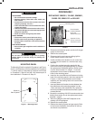
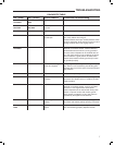
5. Position the provided mounting panel with the
arrow on the front of the panel pointing up. Position
the replacement 50A66-843 ignition control board
over the holes marked "A" in figure 1. Insert the
replacement control stand-off fasteners into the
holes in the mounting panel.
6. Insert the four provided stand-off fasteners into the
back of the mounting panel in the holes marked "B"
in figure 1. Insert the replacement control board
assembly into the existing holes in the control box
or blower panel.
7. Insert provided circuit breaker in series between the
blue transformer wire connecting position 3 on the
12-pin connector to the transformer (TH), optional 4"
blue wire provided for transformers that have a quick-
connect terminal.
8. Connect the remaining 120 VAC hot and neutral wires
and the flame sense wire to the replacement control
per table 1, page 4.
9. Affix wiring diagram 5001-6973 adjacent to the
existing unit wiring diagram.
10. Replace the access panel.
11. Restore the electrical power and gas supply. Refer
to the furnace installation instructions for start-up
and check-out procedures.
PROCEDURE 1
B B
B B
A A
A A
C
C
C
C
Arrow on
front of panel
Figure 1 – Mounting Panel
Photo 1
MOUNTING PANEL
The Mounting Panel is required in Procedure 1 and Proce-
dure 2. It will become part of the installation for Procedure
1. It will be used as a template for locations to drill holes
in Procedure 2, Step 4A and 4B. It will become part of
the installation in Procedure 2, Step 4C.
Mounting panel
Circuit breaker
in series between
Pin 3 and
Transformer (TH)
Optional 4" blue
wire to connect to
Transformer (TH)