


6
Fig. 11 - Inside of front cover
Break tab
to have LEDs
on with cover
installed
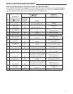
INSTALLER/CONFIGURATION MENU
1) Outdoor / Condenser Configuration. Select the num-
ber type A/C (air conditioner) HP Heat Pump and number
of stages. The appropriate Color (A/C= Amber, Heat
Pump=Green) LED will illuminate for the configured Y/Y2
terminals.
2) Indoor / Heat Configuration. Select the number type
GA (Gas) EL (electric) and Fan and number of stages.
The appropriate Color (Amber if gas, Green if electric)
LED will illuminate for the configured W/W2 terminals.
3) B or O Terminal Configuration. If condenser is heat
pump configured then Select either O (default) or B
terminal output configuration. The B/O LED will illuminate
the appropriate color (Amber if B, Green if O)
4) Heat Cycle Rate. Select either FA fast (default) or SL
slow cycle rate. If longer cycles are desired then set to
SL.
5) Cool Cycle Rate. Select either FA fast (default) or SL
slow cycle rate. If longer cycles are desired then set to
SL.
6) Auxiliary Cycle Rate. If condenser is heat pump select
either FA fast (default) or SL slow cycle rate. If longer
cycles are desired then set to SL.
7) Energy Management Recovery. Select either On or Off.
With a selection of On the system will start temperature
setback recovery early to reach the program setpoint at
the program start time. A selection of Off will start the
recovery period at the program start time.
8) Outdoor Remote Sense. A selection of On enables the
display of outdoor temperature with the connection of
F145-1378 outdoor remote sensor to the control.
9) Auxiliary Off. When condenser is heat pump configured
and outdoor sensor is connected, the option of locking
out the auxiliary heat based on outdoor ambient tem-
perature becomes available. Default is Off with a selec-
tion range from 80 degrees to 35 degrees in 1 degree
increment. When outdoor ambient is above the selected
temperature the auxiliary stages are disabled.
10) Dual Fuel Config. When condenser is heat pump and
indoor heat is gas and outdoor sensor is connected. A
selection from 0 to 50 in one degree increment is avail-
able. The Auxiliary/fossil fuel system is enabled, the heat
pump is disabled when the outdoor ambient temperature
is at or below the selection.
11) Dehumidification. Select from Off (default) to a setting
range from 40% to 80% Rh. If Rh is above setting, a
cooling call is initiated. To turn this feature Off raise set-
ting to its highest level 80%
12) Independent Dehumidification. Selection of Off (de-
fault) or On. When On is selected the DHM2 output is
active when humidity level is above the desired dehu-
midification setting.
13) Humidification. Select from Off (default) to a setting
range from 20% to 60% Rh. If Rh is below setting HM2
output is active with a call for heat. To turn this feature Off
lower setting to its lowest level 20%.
14) Independent Humidification. Selection of Off (default)
or On. When On is selected the HM2 output operates
when humidity level is below the desired humidification
setting.
15) Compressor Lockout. Selection of Off (default) or On.
When On is selected the control will invoke a 5 minute
delay between compressor cycles.
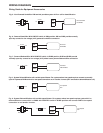
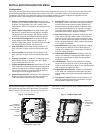
Configuration
Control can be configured at the equipment by utilizing the configuration plug in tool (F4-1400). The tool mounts to the back
of the interface and plugs into the bottom of the control via the RJ-11 connection. (Note: You cannot have two interfaces
connected to the control at the same time). With control powered, interface is used to configure the application and for
operational checks. Once configured, the interface can be installed in living area.
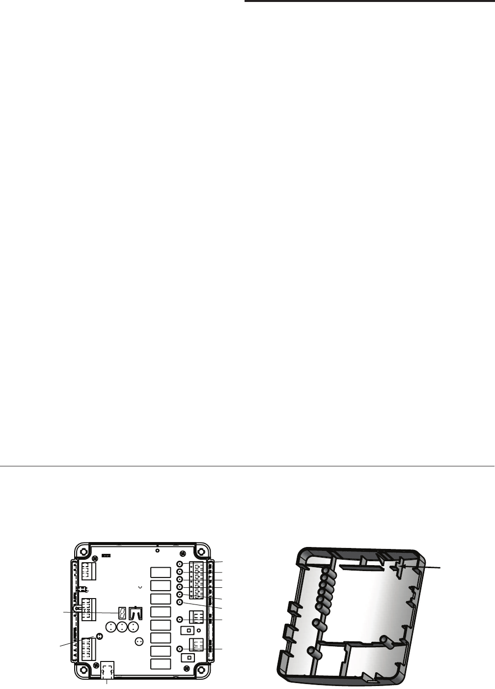
W/E
W2
Y
Y2
G
O/B
HM
DHM
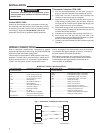
Fig. 10 - LED locations
Fig. 11 - Inside of front cover
Break tab
to have LEDs
on with cover
installed
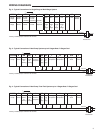
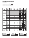
After Advanced Installer Configuration, LEDs on the control
will indicate the selections of the thermostat. The following
tables show the LED indications. Remove control cover to
view LEDs. To view LEDs with cover installed, break off tab
on inside of cover.
W/E
W2
Y
Y2
G
O/B
HM
DHM
RJ-11 Connection for
Configuration Plug-In tool
System
7-Segment
LED for Comfort
Alert and
Communication
Codes