


4
Wiring Guide for Equipment Accessories
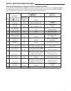
WIRING DIAGRAMS
HM
HM2
Powered
Humidifier
DHM
DHM2
Powered
Dehumidifier
HM
HM2
Non-Powered
Humidifier
Transformer
R
C
R
C
DHM
DHM2
Low Speed
Fan
DHM
DHM2
Low Speed
Fan
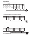
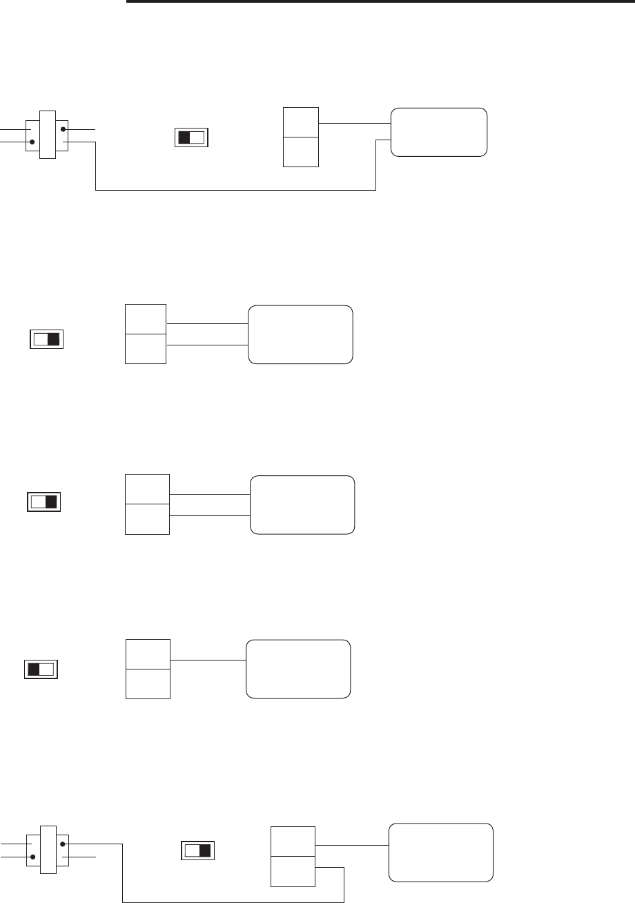
Fig. 5 - Non-Powered Humidifier. HM terminal provides system 24 V on call for humidification
Fig. 6 - Powered Humidifier. With HM DRY switch in HM2 position, HM and HM2 provide normally
open dry contact for low voltage (24 V) powered humidifier connection.
Fig. 7 - Powered Dehumidifier. With DHM DRY switch in DHM2 position, DHM and DHM2 provide
normally open dry contact for low voltage (24 V) whole house powered dehumidifier connection.
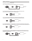
Fig. 8 - System Dehumidification with variable speed blower. For systems where low speed requires connect to normally
open 24 V powered DHM terminal for low speed connection on air handler / furnace (24 V removed on dehumidification call).
Fig. 9 - System Dehumidification with variable speed blower. For systems where low speed requires system 24 V on
dehumidification connect 24 V to DHM2 with DHM DRY switch in DHM2 position and connect DHM to low speed
connection on air handler/ furnace.
Transformer
HM DRY
RH HM2
HM DRY
RH HM2
DHM DRY
RH DHM2
DHM DRY
RH DHM2
DHM DRY
RH DHM2