


3
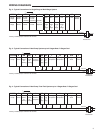
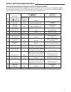
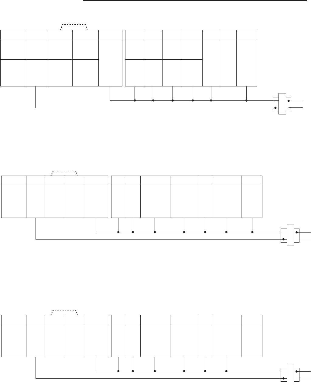
SYSTEM R RH RC C W/E W2 Y Y2 G O/B L
Single
Stage
24 VAC
Power
24 VAC
Power
for Heating
24 VAC
Power
for Cooling
24 VAC
Common
Required
Heat N/A Cool N/A Fan N/A System
Monitor
Multi
Stage
24 VAC
Power
24 VAC
Power
24 VAC
Power
Heat
mode
1
st
stage
Heat
mode
2
nd
stage
Cool
mode
1
st
stage
Cool
mode
2
nd
stage
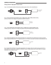
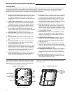
WIRING DIAGRAMS
CLASS II
Transformer
120 VAC
NEUTRAL
24 VAC
HOT
Fig. 2 - Typical Connection of a Single Stage or Multi-Stage System
*Factory installed jumper between RH and RC
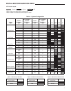
SYSTEM R RH RC C W/E W2 Y Y2 G O/B L
Heat
Pump
24 VAC
Power
24 VAC
Power
for
Heating
24 VAC
Power
for
Cooling
24 VAC
Common
Required
Aux /
Em
1
st
stage
Aux /
Em
2
nd
stage
1
st
stage
Compressor
2
nd
stage
Compressor
Fan Changeover
Valve
System
Monitor
CLASS II
Transformer
120 VAC
NEUTRAL
24 VAC
HOT
Fig. 3 - Typical Connection of Heat Pump System up to 4 Stages Heat / 2 Stages Cool
*Factory installed jumper between RH and RC
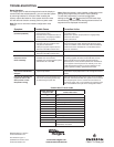
SYSTEM R RH RC C W/E W2 Y Y2 G O/B L
Heat
Pump
24 VAC
Power
24 VAC
Power
for
Heating
24 VAC
Power
for
Cooling
24 VAC
Common
Required
Fossil
Fuel
1
st
stage
Fossil
Fuel
2
nd
stage
1
st
stage
Compressor
2
nd
stage
Compressor
Fan Changeover
Valve
System
Monitor
CLASS II
Transformer
120 VAC
NEUTRAL
24 VAC
HOT
Fig. 4 - Typical Connection of Heat Pump / Dual Fuel System up to 4 Stages Heat / 2 Stages Cool
*Factory installed jumper between RH and RC
*
*
*