


7
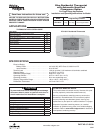
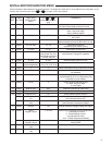
INSTALLER/CONFIGURATION MENU
temperature and press Auto Schedule. This value will be
copied into all the morning, day and evening program
periods. The night program periods will have a 6°F set back.
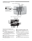
16) Select Remote Temperature Sensor – This control
allows one wired remote temperature sensor (indoor,
F145-1328, or outdoor, F145-1378) be connected to it and
indicates the measured temperature in clock digits. This
menu enables you to select the remote sensor and also
confi gure it as indoor or outdoor temperature sensor. Fac-
tory default is off. Select Remote On and Remote in (for
indoor) or Outdoor Remote.
Local Temperature Sensor disable – This is applicable
only when indoor remote temperature sensor is enabled.
Factory default is Loc On. You can make it Loc Off if you
desire by using
or buttons. Then, only the indoor
remote temperature reading will be used for control
17) Select Daylight Saving Time Calculation – This feature
will allow the thermostat to calculate the DST automati-
cally and apply it to the Real Time Clock display. Default
On. Use or touch keys to select the feature OFF.
18) Keypad Lockout – This step allows you to select the type
of lockout or limited range security required. If no lock-
out or limited range security is required, press MENU to
advance the menu.
Three security settings are available in this menu item.
Use the
or buttons to select the lockout desired.
Lockout selections are:
"Keypad Lockout and L" = Total Lockout. Total Lockout
locks all keys.
"Keypad Lockout and P" = Partial Lockout. Partial Lock-
out allows only the
or buttons to operate within
your set temperature limits.
"Keypad Lockout and Limit" prevents changing the
temperature limits in the Confi guration Menu.
Press Menu after selecting the type of lockout.
"Keypad Lockout Combination Number Selection"
Display will read "000" "Keypad Lockout". Note: "000" is
not a valid combination choice.
Skip this step and continue through the remaining confi gu-
ration menu items if you require an Air Filter Change out
indicator or Humidifi er Pad Change out indicator by press-
ing the MENU button to advance.
Return to this point when you are ready to start your
selected lock-out and continue by:
Press
. Display will read "001".
Pressing
or buttons to select your keypad lock-
out combination number.
Record the number you select for future use.
Press MENU or RunSched to exit the menu. The security
feature you select will start. The system button will remain
active for 10 seconds to allow setting Heat, Off, Cool or
Auto.
19) Limited Heat Range – This feature provides a maximum
setpoint temperature for heat. The default setting is 99°F. It
can be changed between 62°F and 98°F by pressing the
or button.
20) Limited Cool Range – This feature provide a minimum
setpoint temperature for cool. The default setting is 45°F. It
can be changed between 46°F and 82°F by pressing the
or button.
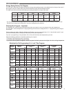
21) Select Filter Replacement Reminder and Set Run Time
Select the "Change Filter" reminder On or OFF. If se-
lected On, press MENU to select the time period from 25
to 1975 hours in 25 hours increments. In a typical system,
200 hours (default) of run time is approximately 30 days.
After the selected time of blower operation, the thermostat
will display "Change Filter" as a reminder to change or
clean your air fi lter. When "Change Filter" is displayed,
press MENU or RUN SCHED button to clear the display
and restart the time to the next fi lter change.
22) Change UV Lamp – This feature allows the thermostat to
display the words "Change UV Lamp" (Call for Service
of UV bulb) after a set time of UV bulb operation. This is
a reminder to maintain your UV system at optimum level
of operation. When enabled the factory set interval for
"Change UV Lamp" to be displayed is 350 days of UV
bulb operation and can be adjusted in 25 day increments.
This should be adjusted with respect to the bulb's recom-
mended maintenance schedule.
When "Change UV Lamp" is displayed, you can clear it
by pressing MENU.
23) Select Reversing Valve Output – The O/B option is
factory set at "O" position. This will accommodate the
majority of heat pump applications, which require the
changeover relay to be energized in COOL. If the thermo-
stat you are replacing or the heat pump being installed
with this thermostat requires a "B" terminal, to energize
the changeover relay in HEAT, the O/B option should be
set at "B" position.