


3
Single Stage
System
RC RH C Y* W* G O/B 6 L
CLASS II
TRANSFORMER
HOT
24VAC
NEUTRAL
120VAC
Call for heat
24 volt
power for
cooling
24 volt
power for
heating
24 volt
common
(optional for
system
operation,
required for
remote
sensor and
system status
indicator)
Call for cool
Blower/Circulator fan
energized on a call
for cool or Fan On
(also energized in
heating if configured
for Electric Heat)
Installer
Configuration
Menu selects
“O” or “B” for
changeover
function. Set
to “O” terminal
energized in Cool
& Off mode. Set
to “B” terminal
energized in Heat
Power closed
connection for
SPDT 3-wire
zone valve
System
status
Indicator for
sytems
with “L” terminal
connection
WIRING CONNECTIONS
Refer to equipment manufacturers' instructions for specifi c
system wiring information. After wiring, see CONFIGURA-
TION section for proper thermostat confi guration.
Wiring diagrams shown are for typical systems and describe
the thermostat terminal functions.
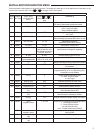
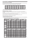
TERMINAL DESIGNATION DESCRIPTIONS
Terminal Designation Description
O/B ........................................... Changeover valve for heat pump energized constantly in cooling and off/heating
Y ............................................ Compressor Relay
G ............................................ Fan Relay
RC ............................................Power for Cooling
RH ............................................Power for Heating
C ............................................ Common wire from secondary side of cooling (Optional). Required for fault indication, continuous back-
light operation or remote temperature sensor operation
W ........................................... Heat Relay (Stage 1)
- ............................................ Common (DC) for wired remote temperature sensor
S ............................................Frequency signal from remote temperature sensor
+ ............................................ Power (DC) to remote temperature sensor
L ............................................ Compressor diagnostic indicator for systems with diagnostic connection typically found on Heat pump
systems or with Copeland's Comfort Alert
WIRING DIAGRAMS
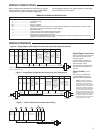
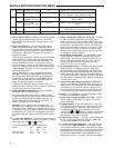
Figure 2 – Single Stage or Heat Pump with no Auxiliary Heat with Single Transformer
Single Stage Connections
Refer to equipment manufacturers'
instructions for specifi c system
wiring information.
This thermostat is designed to
operate a single-transformer or
two-transformer system.
This thermostat is confi gured for
use with the following fossil fuel
systems:
SINGLE STAGE gas, oil or
electric.
After wiring, see INSTALLER
CONFIGURATION section for
proper thermostat confi guration.
*Jumper Y to W required for heat pump systems not compatible with heat pump systems that
require an auxiliary heat output.
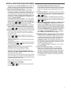
Figure 3 – Single Stage System (No Heat Pump) with Two Transformers
NOTE: If continuous backlight or
hardwired power input are desired
but do not function in both HEAT
and COOL modes, cut the heating
transformer 24V wires and tape off.
Connect the neutral circuit discon-
nected from the heating transformer
to the neutral circuit of the cooling
transformer. Disconnect the wire to
the RH terminal and install a jumper
between RH and RC. Depending on
the system requirements, replace
the cooling transformer with a 75VA
class II transformer if needed.
Single
Stage
System
RC RH C Y W6L
Call for heat
24 volt
power for
cooling
24 volt
power for
heating
24 volt
common
(optional
for system
operation,
required
for remote
sensor)
Heat mode-1st
stage,
Cool mode-1st
stage,
(Compressor)
G
Blower/Circulator fan
energized on a call
for cool or Fan On
(also energized in
heating if configured
for Electric Heat)
O
Installer
Configuration
Menu selects
“O” or “B” for
changeover
function. Set
to “O” terminal
energized in Cool
& Off mode. Set
to “B” terminal
energized in
Heat
Power closed
connection for
SPDT 3-wire
zone valve
CLASS II
TRANSFORMER
HOT
24VAC
NEUTRAL
120VAC
COOLING
CLASS II
TRANSFORMER
HOT
24VAC
NEUTRAL
120VAC
HEATING
120VAC
System
status
Indicator for
sytems
with “L” terminal
connection
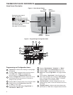
Single Stage
3-wire
Zone Valve
application
Blower/Circulator
Fan Energized
Opens
Valve
(4)
Constant
24 Volt
(Com-
mon)
24 Volt
(Hot)
Cool
System
6
Y
W
C
RC
CLASS II
TRANSFORMER
HOT
24VAC
NEUTRAL
120VAC
24 Volt
(Hot)
Heat
(5)
RH
G
Jumper
Closes
Valve
(6)
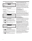
Figure 4 – 3-Wire (SPDT) Heat Only Zone Valve Wiring