


4
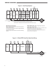
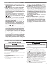
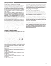
Single Stage
3-wire
Zone Valve
application
Blower/Circulator
Fan Energized
Opens
Valve
(4)
Constant
24 Volt
(Com-
mon)
24 Volt
(Hot)
Cool
System
6
Y
W
C
RC
CLASS II
TRANSFORMER
HOT
24VAC
NEUTRAL
120VAC
24 Volt
(Hot)
Heat
(5)
RH
G
Jumper
Closes
Valve
(6)
Figure 5 – 3-Wire (SPDT) Heat Only Zone Valve Wiring
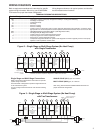
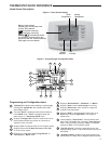
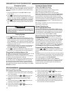
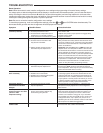
Figure 4 – Heat Pump Systems
Heat Pump 1
(HP1)
Heat Pump 2
(HP2)
O
Energized in
Cool Mode
B
Energized in
Heat, Off,
Emergency
Mode
No
Output
2nd
Stage
(Com-
pressor)
Heat and
Cool Mode
1st Stage
(Compressor)
Blower/
Circulator Fan
Energized on
Call for Heat
or Cool.
Set Elect/Gas
Option for
Emergency
mode
Heat Mode - 3rd
Stage, Emergency
Mode - 2nd Stage
Heat Mode-4th
Stage. Emergency
Mode - 2nd Stage
Heat Mode - 2nd
Stage, Emergency
Mode - 1st Stage
Heat Mode - 3rd
Stage, Emergency
Mode - 1st Stage
Optional*
24 Volt
(Com-
mon)
Diagnostic
Indicator
or System
Malfunction
Switch
24 Volt
(Hot)
Cool
System
Y
+
W/E
C
L
RC
CLASS II
TRANSFORMER
HOT
24VAC
NEUTRAL
120VAC
24 Volt
(Hot)
Heat
RH
Jumper
Y2
+
W2
G
Comfort Alert II Module
or Similar System
Diagnostic Module
See Module Instructions
for details
O/B
+
Note: Dual Fuel option
de-energizes Heat mode
stage 1 (compressor)
when auxiliary heat
is energized
+
Note: Dual Fuel option
de-energizes Heat mode
stage 1 (compressor)
when auxiliary heat
is energized
+
Note: Dual Fuel option
de-energizes Heat mode
stage 1 (compressor)
when auxiliary heat
is energized
+
Note: Dual Fuel option
de-energizes Heat mode
stage 1 (compressor)
when auxiliary heat
is energized
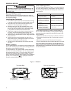
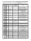
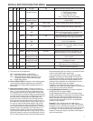
WIRING DIAGRAMS
Heat Pump Connections
Refer to equipment manufacturers' instructions for specifi c
system wiring information.
This thermostat is designed to operate a single-transformer
or two-transformer system.
You can confi gure the thermostat for use with the following
systems:
HEAT PUMP TYPE 1 (HP 1). Single stage compressor
system; gas or electric backup.
HEAT PUMP TYPE 2 (HP 2). Multi-stage compressor or two
compressor system with gas or electric backup.
After wiring, see INSTALLER CONFIGURATION section for
proper thermostat confi guration.
* Common connection required for diagnostic or malfunction indication.
+
Dual Fuel option, if selected turns off compressor(s) when Auxiliary stages energize.