


3
WIRING DIAGRAMS
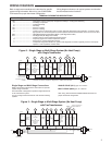
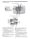
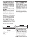
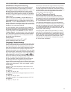
Figure 2 – Single Stage or Multi-Stage System (No Heat Pump)
with Single Transformer
Single
Stage 1
(SS1)
Multi-
Stage 2
(MS2)
O
Energized Constantly
in
Cool Mode
B
Energized Constantly
in Heat, Off,
Emergency
Mode
No
Output
Cool
Mode
2nd
Stage
Cool Mode
1st Stage
Blower/
Circulator
Fan Energized
on Call for
Cool (and
Heat if
configured
for Electric
Heat)
No Output
Heat Mode
2nd Stage
Heat
Mode
1st Stage
Optional*
24 Volt
(Com-
mon)
24 Volt
(Hot)
Cool
System
Y
G
W/E
C
L
RC
CLASS II
TRANSFORMER
HOT
24VAC
NEUTRAL
120VAC
24 Volt
(Hot)
Heat
RH
Y2
W2
Jumper
Diagnostic
Indicator
Input
or
System
Malfunction
Switch
Input
Comfort Alert II Module
or Similar System
Diagnostic Module
See Module Instructions
for details
O/B
* Common connection required for diagnostic or malfunction indication.
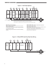
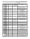
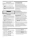
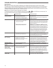
Figure 3 – Single Stage or Multi-Stage System (No Heat Pump)
with Two Transformers
Single
Stage 1
(SS1)
Multi-
Stage 2
(MS2)
No
Output
Cool
Mode
2nd
Stage
Cool Mode
1st Stage
Blower/
Circulator
Fan Energized
on Call for
Cool (and
Heat if
configured
for Electric
Heat)
No Output
Heat Mode
2nd Stage
Heat
Mode
1st Stage
Optional
24 Volt
(Com-
mon)
Diagnostic
Indicator
(Optional)
24 Volt
(Hot)
Cool
System
Y
G
W/E
C
L
RC
CLASS II
TRANSFORMER
HOT
24VAC
NEUTRAL
120VAC
24 Volt
(Hot)
Heat
RH
120VAC
Remove Jumper Wire
between RH & RC
HOT
24VAC
NEUTRAL
CLASS II
TRANSFORMER
HEATING
COOLING
Y2
W2
Jumper
O/B
O
Energized Constantly
in
Cool Mode
B
Energized Constantly
in Heat, Off,
Emergency
Mode
Single Stage and Multi-Stage Connections
Refer to equipment manufacturers' instructions for specifi c
system wiring information.
This thermostat is designed to operate a single-transformer
or two-transformer system.
You can confi gure the thermostat for use with the following
systems:
SINGLE STAGE (SS 1) gas, oil or electric.
MULTI-STAGE (MS 2) gas, oil or electric.
After wiring, see INSTALLER CONFIGURATION section for
proper thermostat confi guration.
Refer to equipment manufacturers' instructions for specifi c
system wiring information. After wiring, see CONFIGURA-
TION section for proper thermostat confi guration.
Wiring diagrams shown are for typical systems and describe
the thermostat terminal functions.
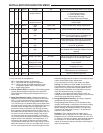
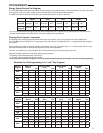
TERMINAL DESIGNATION DESCRIPTIONS
Terminal Designation Description
O/B ........................................... Changeover valve for heat pump energized constantly in cooling and off/heating
Y2 ............................................ 2nd Stage Compressor
Y ............................................ Compressor Relay
G ............................................ Fan Relay
RC ............................................Power for Cooling
RH ............................................Power for Heating
C ............................................ Common wire from secondary side of cooling (Optional). Required for fault indication, continuous back-
light operation or remote temperature sensor operation 6 Powered closed 3rd wire for 3-wire zone valve
W/E ........................................... Heat Relay/Emergency Heat Relay (Stage 1) (3rd Stage Heat in HP2)
W2 ............................................ 2nd Stage Heat (4th Stage Heat in HP2)
- ............................................Common (DC) for wired remote temperature sensor
S ............................................Frequency signal from remote temperature sensor
+ ............................................ Power (DC) to remote temperature sensor
L ............................................ Compressor diagnostic indicator for systems with diagnostic connection typically found on Heat pump
systems or with Copeland's Comfort Alert