


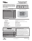
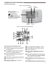

Blue Universal Thermostat
with Automatic Heat/Cool
Changeover Option
Model Programming Choices
1F95-0671
7 Day 5/1/1 Day Non-Programmable
www.white-rodgers.com
PART NO. 37-6979A
0908
Single Stage, Multi-Stage, Heat Pump
Installation and Operating Instructions for Model:
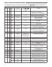
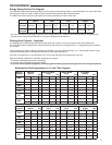
APPLICATIONS
THERMOSTAT APPLICATION GUIDE
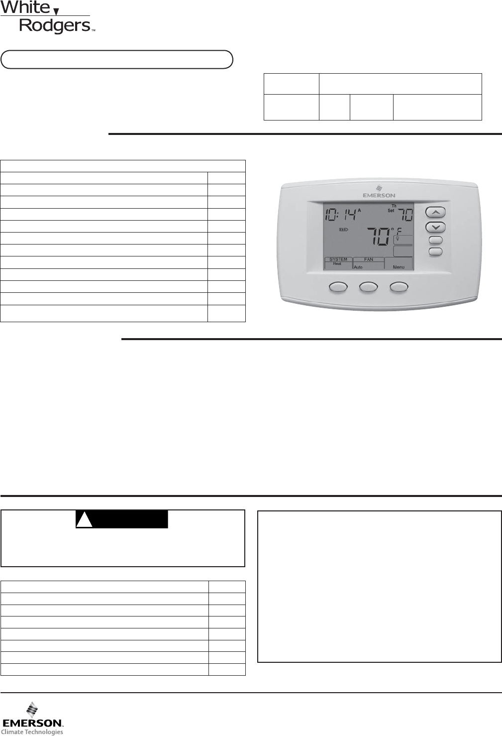
1F95-0671 Universal Thermostat
SPECIFICATIONS
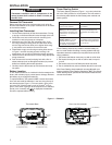
To prevent electrical shock and/or equipment damage,
disconnect electric power to system at main fuse or
circuit breaker box until installation is complete.
CAUTION
!
Save these instructions for future use!
FAILURE TO READ AND FOLLOW ALL INSTRUCTIONS
CAREFULLY BEFORE INSTALLING OR OPERATING THIS
CONTROL COULD CAUSE PERSONAL INJURY AND/OR
PROPERTY DAMAGE.
Description
Heat Pump (No Aux. or Emergency Heat) Yes
Heat Pump (with Aux. or Emergency Heat) Yes
Systems with up to 4 Stages Heat, 2 Stages Cool Yes
Heat Only Systems Yes
Millivolt Heat Only Systems – Floor or Wall Furnaces Yes
Cool Only Systems Yes
Gas or Oil Heat Yes
Electric Furnace Yes
Hydronic (Hot Water) Zone Heat – 2 Wires Yes
Hydronic (Hot Water) Zone Heat – 3 Wires Yes
Wired Remote Temperature Sensor (Indoor or Outdoor) Yes
Dual Fuel Feature (Heat Pump Mode, Outdoor Remote
Re
q
uired
)
Ye s
ATTENTION: MERCURY NOTICE
This product does not contain mercury. However, this prod-
uct may replace a product that contains mercury.
Mercury and products containing mercury must not be
discarded in household trash. Do not touch any spilled
mercury. Wearing non-absorbent gloves, clean up any
spilled mercury and place in a sealed container. For proper
disposal of a product containing mercury or a sealed
container of spilled mercury, place it in a suitable shipping
container. Refer to www.white-rodgers.com for location to
send product containing mercury.
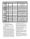
Index Page
Installation 2
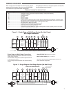
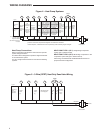
Wiring Diagrams 3
Thermostat Quick Reference 5
Installer Confi guration Menu 6
Operating Your Thermostat 9
Programming 10
Troubleshooting 14
Electrical Rating:
Battery Power. . . . . . . . . . . . . . . . . . . . . . . . . . mV to 30 VAC, NEC Class II, 50/60 Hz or DC
Input-Hardwire . . . . . . . . . . . . . . . . . . . . . . . . . 20 to 30 VAC
Terminal Load . . . . . . . . . . . . . . . . . . . . . . . . . . . . . 1.5A per terminal, 2.5A maximum all terminals combined
Setpoint Range . . . . . . . . . . . . . . . . . . . . . . . . . . . . 45 to 99°F (7 to 32°C)
Differential (Single Stage) . . . . . . . . . . . . . . . . . . . . Heat 0.6°F; Cool 1.2°F
Differential (Multi-Stage) . . . . . . . . . . . . . . . . . . . . . Heat 0.6°F; Cool 1.2°F
Differential (Heat Pump) . . . . . . . . . . . . . . . . . . . . . Heat 1.2°F; Cool 1.2°F
Operating Ambient. . . . . . . . . . . . . . . . . . . . . . . . . . 32°F to +105°F (0 to +41°C)
Operating Humidity . . . . . . . . . . . . . . . . . . . . . . . . . 90% non-condensing max.
Shipping Temperature Range . . . . . . . . . . . . . . . . . -40 to +150°F (-40 to +65°C)
Dimensions Thermostat. . . . . . . . . . . . . . . . . . . . . . 4.2"H x 6.4"W x 1.7"D