


4
Remove the Old Thermostat
1. Turn off power to the heating and cooling system.
2. Remove the front cover of the old thermostat, this usually
pulls off.
3. Loosen the screws that hold the thermostat to the wall.
4. Identify each wire attached to the old thermostat.
5. Disconnect the wires from old thermostat one at a time. DO
NOT LET WIRES FALL BACK INTO THE WALL.
Install the New Thermostat
1. Open the battery door and detach the new thermostat
cover from the base.
2. With the base flush against the wall, mark mounting hole
locations on wall.
3. Move base out of the way and drill mounting holes.
4. Push wires through wire opening.
5. Position the base on the wall again and screw the mounting
screws into the wall anchors.
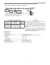
6. Connect each wire coming from the wall to its corresponding
terminal as shown in Fig. 2 on page 7.
NOTE
Wires will not be connected to all terminals of the terminal
block.
Installation
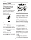
Figure 1. Thermostat Base
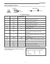
Set Switches
Fan (Ele/Gas) Switch
For Electric Heat, heat pump or any system that requires the
thermostat to turn on the blower on a call for heat– place the
FAN (Ele/Gas) switch (Fig. 1) in the ON position. For Auxiliary
and Emergency Heat systems that have a fan control to turn
on the blower (independent of the thermostat) place switch in
the OFF position.
O/B Terminal Switch Selection
The O/B switch on this thermostat is factory set to the “O”
position. This will accommodate the majority of heat pump
applications, which require the changeover relay to be
energized in COOL. If the thermostat you are replacing or the
heat pump being installed with this thermostat requires a “B”
terminal, to energize the changeover relay in HEAT, the O/B
switch must be moved to the “B” position.
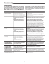
Check Thermostat Operation
Heating System
1. Move SYSTEM switch to HEAT position. If the heating
system has a standing pilot, be sure to light it.
2. Press to adjust thermostat setting to 1° above room
temperature. The heating system should begin to operate.
3. Press to adjust temperature setting below room
temperature. The heating system should stop operating.
Fan Operation
If your system does not have a G terminal connection, skip to
Heating System.
1. Move SYSTEM switch to OFF position.
2. Move fan switch to ON position. The blower should begin
to operate.
3. Move fan switch to AUTO position. The blower should stop
immediately.
Cooling System
1. Move SYSTEM switch to COOL position.
2. Press
to adjust thermostat setting below room
temperature. The blower should come on immediately on
high speed, followed by cold air circulation. However, if the
setpoint temperature is flashing, the compressor lockout
feature is operating (see Configuration menu, item 5).
3. Press to adjust temperature setting above room
temperature. The cooling system should stop operating.
Emergency System
EMER bypasses the Heat Pump to use the heat source wired
to terminal W2 on the thermostat. EMER is typically used
when compressor operation is not desired, or you prefer back-
up heat only.
1. Move SYSTEM switch to EMER position, EMER will flash
on the display.
2. Press
to adjust the thermostat above room tempera-
ture. The Aux heating system will begin to operate. The
Flame icon ( ) will display flashing to indicate that the
Aux system is operating.
3. Press to adjust the thermostat below room tempera-
ture. The AUX heating system should stop operating
Wire Terminal Block
R
C
O/B
W2
Y
G
L
Insert
Wire
Press down
Mounting
Hole
Mounting
Hole
Opening
for wires
O/B
Switch
Battery
Door
F A N
(Ele/Gas)
Switch