


5
OPERATIONOPERATION
OPERATIONOPERATION
OPERATION
Figure 6 – Thermostat display, buttons and switchesFigure 6 – Thermostat display, buttons and switches
Figure 6 – Thermostat display, buttons and switchesFigure 6 – Thermostat display, buttons and switches
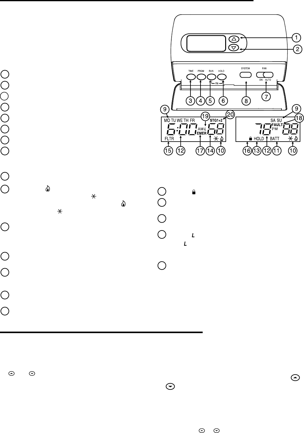
Figure 6 – Thermostat display, buttons and switches
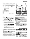
Before you begin programming your thermostat, you should be
familiar with its features and with the display and the location
and operation of the thermostat buttons. Your thermostat
consists of two parts: the thermostat cover and the base. To
remove the cover, pull it straight out from the base. To replace
the cover, line up the cover with the base and press until the
cover snaps onto the base.
The Thermostat Buttons and SwitchesThe Thermostat Buttons and Switches
The Thermostat Buttons and SwitchesThe Thermostat Buttons and Switches
The Thermostat Buttons and Switches
1
Raises temperature setting
2
Lowers temperature setting.
3
TIME button.
4
PRGM (program) button.
5
RUN (run program) button.
6
HOLD temperature button.
7
FAN switch (
ONON
ONON
ON,
AUTOAUTO
AUTOAUTO
AUTO)
8
SYSTEM button (
COOLCOOL
COOLCOOL
COOL,
AUTOAUTO
AUTOAUTO
AUTO,
HEATHEAT
HEATHEAT
HEAT,
EMEREMER
EMEREMER
EMER,
OFFOFF
OFFOFF
OFF)
The DisplayThe Display
The DisplayThe Display
The Display
9
Indicates day of the week.
10
Flame iconFlame icon
Flame iconFlame icon
Flame icon ( ) is displayed when the system is in
HEAT HEAT
HEAT HEAT
HEAT mode.
Snowflake icon Snowflake icon
Snowflake icon Snowflake icon
Snowflake icon (
) is displayed when
the system is in
COOL COOL
COOL COOL
COOL mode.
Flame iconFlame icon
Flame iconFlame icon
Flame icon ( ) and
Snowflake icon Snowflake icon
Snowflake icon Snowflake icon
Snowflake icon (
) are displayed simultaneously
when thermostat is in
AUTO AUTO
AUTO AUTO
AUTO mode.
11
Displays
“BATT” “BATT”
“BATT” “BATT”
“BATT” when the 2 "AA" batteries are low and
should be replaced. Only
“BATT” “BATT”
“BATT” “BATT”
“BATT” and
“LO” “LO”
“LO” “LO”
“LO” in the
minutes field are displayed when batteries are low and
with no system power.
12
Alternately displays current time and temperature. Dis-
plays
“LO” “LO”
“LO” “LO”
“LO” in the minutes field when batteries are low.
13
The word
“HOLD” “HOLD”
“HOLD” “HOLD”
“HOLD” is displayed when the thermostat is
in the HOLD mode.
“HOLD” is displayed flashing“HOLD” is displayed flashing
“HOLD” is displayed flashing“HOLD” is displayed flashing
“HOLD” is displayed flashing
when the thermostat is in a temporary HOLD mode.when the thermostat is in a temporary HOLD mode.
when the thermostat is in a temporary HOLD mode.when the thermostat is in a temporary HOLD mode.
when the thermostat is in a temporary HOLD mode.
14
Displays currently programmed set temperature (this
is blank when SYSTEM is OFF).
15
Displays
“FLTR” “FLTR”
“FLTR” “FLTR”
“FLTR” when the system has run for the
programmed filter time period as a reminder to change
or clean your filter.
16
Display ( ) when in keypad lockout mode.
17
“EMER” “EMER”
“EMER” “EMER”
“EMER” is displayed flashing when the system is in
EMER mode.
18
The word
“FAULT”“FAULT”
“FAULT”“FAULT”
“FAULT” will be displayed when there is a
malfunction in the HEAT/COOL system.
19
Display ( ) when limited HEAT/COOL range is activated.
The “
” icon will flash if an attempt is made to adjust
the temperature beyond the limited HEAT/COOL
temperature range.
20
Stage1 & 2Stage1 & 2
Stage1 & 2Stage1 & 2
Stage1 & 2 indicators: The thermostat shall indicate
when the first and second stage is energized except
in emergency mode. The icon is
“STG 1”“STG 1”
“STG 1”“STG 1”
“STG 1” for the first
stage energized. The icons for the first and second
stage energized are
“STG1+2”“STG1+2”
“STG1+2”“STG1+2”
“STG1+2” located in the upper
right side of the display.
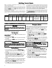
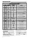
CONFIGURATION MENUCONFIGURATION MENU
CONFIGURATION MENUCONFIGURATION MENU
CONFIGURATION MENU
The configuration menu allows you to set certain thermostat
operating characteristics to your system or personal require-
ments.
Set SYSTEM
button to
OFFOFF
OFFOFF
OFF, then simultaneously press
and to enter configuration menu. The display will
show the first item in the configuration menu.
The configuration menu table summarizes the configuration
options. An explanation of each option follows.
Press SYSTEM
to change to the next menu item. To exit the
menu and return to the program operation, press RUN. If no keys
are pressed within fifteen minutes, the thermostat will revert to
normal operation.
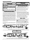
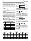
1)
Single Stage, Multi-stage or Heat Pump SystemSingle Stage, Multi-stage or Heat Pump System
Single Stage, Multi-stage or Heat Pump SystemSingle Stage, Multi-stage or Heat Pump System
Single Stage, Multi-stage or Heat Pump System
ConfigurationConfiguration
ConfigurationConfiguration
Configuration – This control can be configured for Heat
Pump or two stage heat/two stage cool multi-stage opera-
tion. The display indicates
“MS 2”“MS 2”
“MS 2”“MS 2”
“MS 2” (default for multi-stage
mode) in the display. The Multi-stage configuration can be
toggled to
“SS1”“SS1”
“SS1”“SS1”
“SS1”,
“HP2”“HP2”
“HP2”“HP2”
“HP2”, or
“HP1”“HP1”
“HP1”“HP1”
“HP1” by pressing the
or
key. In Multi-stage configuration, SYSTEM button will
not have
EMEREMER
EMEREMER
EMERgency mode.
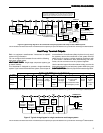
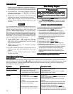
2)
Programs Per Week Programs Per Week
Programs Per Week Programs Per Week
Programs Per Week – This control can be configured for 7
independent day or 5/1/1/ programming or non-program-
mable mode. The display indicates
“7d”“7d”
“7d”“7d”
“7d” as default. The
programs per week can be toggled to
“5d”“5d”
“5d”“5d”
“5d” or
“0d”“0d”
“0d”“0d”
“0d” by
pressing the
or keys. With
“0d”“0d”
“0d”“0d”
“0d” selected for non-