


3
NOTE NOTE
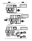
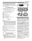
The following wiring diagrams show typical terminal identifica-
tion and wiring. For proper installation, refer to the original
manufacturer's instructions.
Relay contacts shown are thermostatically operated.
C* R
OB
Energized
in HEAT
Cooling
System
Heating
System
Thermostat
Control
Circuit
24 VAC 120 VAC
Hot
Neutral
THERMOSTAT
SYSTEM
Y W
Figure 3. Typical wiring diagram for single transformer systems
Fan
Relay
G
TRANSFORMER
Energized
in COOL
* The 24 Volt neutral connection
to terminal C on the thermostat
is not required if you replace
the batteries once a year with
fresh “AA” Energizer
®
alkaline
batteries.
C* R
Cooling
System
Heating
System
Thermostat
Control
Circuit
24 VAC 120 VAC
Hot
Neutral
THERMOSTAT
SYSTEM
Y W
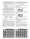
Figure 4. Typical wiring diagram for two-transformer systems with NO safety circuits
Fan
Relay
G
TRANSFORMER
24 VAC120 VAC
Hot
Neutral
TRANSFORMER
TWO COMMONS MUST
BE JUMPERED TOGETHER!
CUT AND
TAPE OFF!
* The 24 Volt neutral connection
to terminal C on the thermostat
is not required if you replace
the batteries once a year with
fresh “AA” Energizer
®
alkaline
batteries.
O
Energized
in COOL
B
Energized
in HEAT
C* R
Cooling
System
Heating
System
Thermostat
Control
Circuit
Limit or
Safety
Switches
Limit or
Safety
Switches
Limit or
Safety
Switches
Limit or
Safety
Switches
24 VAC 120 VAC
Hot
Common
Common
Neutral
THERMOSTAT
SYSTEM
Y W
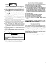
Figure 5. Typical wiring diagram for two-transformer systems with safety circuits in BOTH systems
Fan
Relay
G
HEATING
TRANSFORMER
24 VAC 120 VAC
Hot
Neutral
COOLING
TRANSFORMER
TWO COMMONS MUST
BE JUMPERED TOGETHER!
24 VAC
Accessory
Relay N.O.
Contact
* The 24 Volt neutral connection
to terminal C on the thermostat
is not required if you replace
the batteries once a year with
fresh “AA” Energizer
®
alkaline
batteries.
O
Energized
in COOL
B
Energized
in HEAT