


4
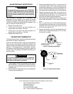
GRC
Y
W
B
A
RH
O
RH W B O Y G RC A
24 VAC
120 VAC
Hot
Neutral
TRANSFORMER
Heat
Relay
Compressor
Relay
Fan
Relay
** *
Factory-Installed Jumper
SYSTEM
THERMOSTAT
WIRING
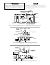
Figure 4. Typical wiring for single transformer heating/cooling system
KEEP THIS
AREA CLEAR
OF WIRES!
Factory-installed
Red Jumper Wire
Factory-installed
Yellow Jumper Wire
* * *
Terminal energized
in cooling
Terminal energized
in heating
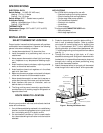
Take care when securing and routing wires so
they do not short to adjacent terminals or rear of
thermostat. Personal injury and/or property dam-
age may occur.
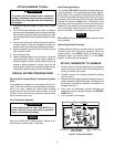
These typical wiring diagrams show only the terminal
identification and wiring hookup. Always refer to wiring
instructions, provided by equipment manufacturer, for
system hookup operation.
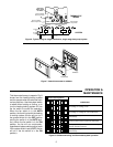
G
RH
W
Factory-installed Jumper
Moveable
Yellow Jumper
SUBBASE
Adjustable Heating
Anticipator
Captive
Screws
System
Switch
COOL
OFF
HEAT
System
Switch
COOL
OFF
HEAT
ON
Fan
Switch
AUTO
Figure 3. Typical wiring diagram (see figs. 4, 5, and 6 for typical system/thermostat wiring)
RC O
Y
A* B
Fixed Cooling
Anticipator
THERMOSTAT
SYSTEM
* Terminal "A" is not for field wiring. See
SPECIAL SYSTEM CONFIGURATIONS
section for proper use of terminal "A".
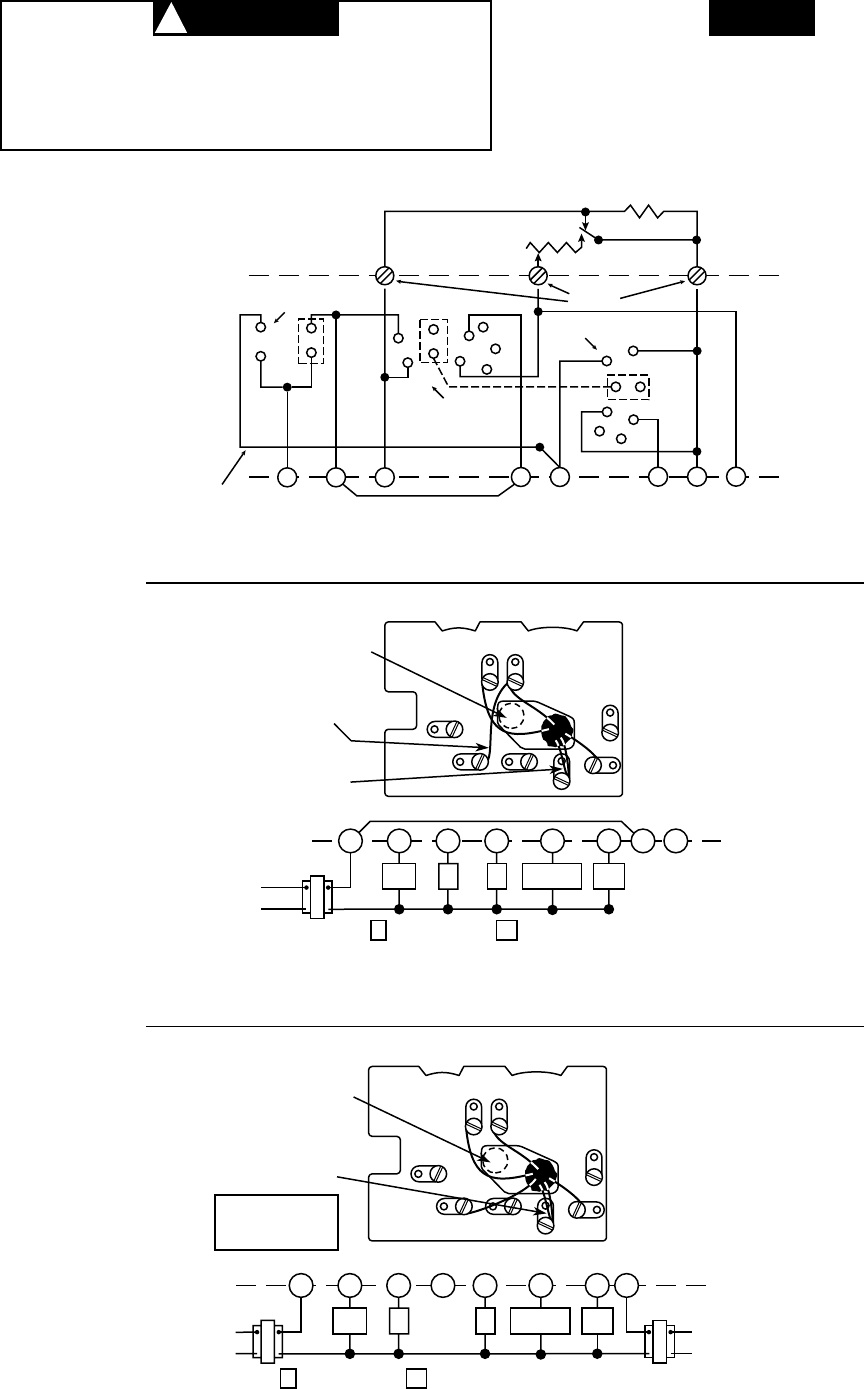
GRC
Y
W
B
A
RH
O
THERMOSTAT
WIRING
Figure 5. Typical wiring for two-transformer heating/cooling system
KEEP THIS
AREA CLEAR
OF WIRES!
Factory-installed
Yellow Jumper Wire
RH W B O Y GA
24 VAC
120 VAC
Hot
Neutral
TRANSFORMER
Heat
Relay
Compressor
Relay
Fan
Relay
** *
SYSTEM
* * *
Terminal energized
in cooling
Terminal energized
in heating
24 VAC
120 VAC
Hot
Neutral
TRANSFORMER
RC
NOTE: Remove factory-
installed jumper between
RC and RH terminals for
this application.
NOTE
CAUTION
!