


2
SPECIFICATIONS
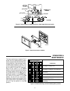
ELECTRICAL DATA
Switch Rating: 24 VAC (30 VAC max.)
Heating - 0.15 to 1.2 Amps
Cooling - 0 to 1.5 Amps
Switch Action: SPST - Sealed mercury switch
Anticipator Rating:
Heating - Adjustable from 0.15 to 1.2 Amps
Cooling - Fixed 24 VAC
THERMAL DATA
Temperature Range: 50°F to 90°F (10°C to 32°C)
Differential: 1°F
APPLICATIONS
The 1F56W-444 is designed for use with
• Standard heating and cooling systems
• Electric heating and cooling systems
• Single stage heat pump systems
• Two-transformer systems
• Electronic air cleaners
• Humidifiers
• Zone dampers
This thermostat CANNOT BE USED with:
• Millivolt systems
• Multi-stage applications
INSTALLATION
SELECT THERMOSTAT LOCATION
Proper location insures that the thermostat will provide a
comfortable home temperature. Observe the following
general rules when selecting a location:
1. Locate thermostat about 5 ft. above the floor.
2. Install thermostat on a partitioning wall, not on an
outside wall.
3. Never expose thermostat to direct light from lamps,
sun, fireplaces or any temperature radiating equip-
ment.
4. Avoid locations close to windows, adjoining outside
walls, or doors that lead outside.
5. Avoid locations close to air registers or in the direct
path of air from them.
6. Make sure there are no pipes or duct work in that part
of the wall chosen for the thermostat location.
7. Never locate thermostat in a room that is warmer or
cooler than the rest of the home, such as the kitchen.
8. Avoid locations with poor air circulation, such as
behind doors or in alcoves.
9. The living or dining room is normally a good location,
provided there is no cooking range or refrigerator on
opposite side of wall.
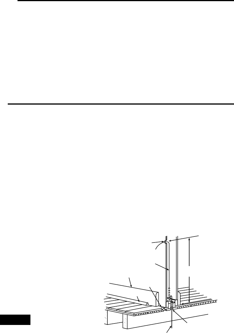
ROUTE WIRES TO LOCATION
All wiring must conform with local and national electrical
codes and ordinances.
1. If an old thermostat being replaced is in a satisfactory
location, and the wiring appears to be in good condi-
tion, use existing wiring. If in doubt, re-wire.
2. If a new location is chosen or if this is a new installa-
tion, thermostat wiring must first be run to the location
selected.
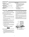
3. Probe for obstructions in partition before drilling
1
⁄2”
hole in wall at selected location. Take up quarter
round and drill a small guide hole for sighting (see
fig. 1). From basement, drill
3
⁄4” hole in partition floor
next to guide hole. In houses without basements, drill
1
⁄2” hole through ceiling and into partition from above
(see fig. 1).
4. Through this hole drop a light chain, or 6” chain
attached to a strong cord. Snag cord in basement with
hooked wire. In houses without basements, drop cord
through hole in ceiling and down partitioning; snag
cord at the thermostat location.
5. Attach thermostat wires to cord and pull thermostat
wires through hole in wall so that 6” of wire protrudes.
NOTE
Approximately
5 feet from floor
1
⁄
2
” hole for
thermostat wire
Stout cord with 6”
chain attached
Baseboard
strip moulding
1
⁄
4
” guide hole
for sighting
Quarter round
removed
3
⁄
4
” hole in floor of partition
Hooked wire for snagging chain
Figure 1. Routing thermostat wires