


3
ATTACH SUBBASE TO WALL
To prevent electrical shock and/or equipment
damage, disconnect electric power to system at
main fuse or circuit breaker box until installation
is complete.
1. Disconnect electrical power at main fuse or circuit
breaker.
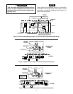
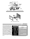
2. Pull wires through opening near center of subbase
and connect wires beneath terminal screws (see figs.
2 through 6 for typical wiring for each application. Also
refer to subsections below for special system configu-
rations).
3. Push excess wiring into wall and plug hole with fire-
resistant material (such as fiberglass insulation) to
prevent drafts from affecting thermostat operation.
4. Position subbase over hole in wall and mark mounting
hole locations on wall.
5. Drill mounting holes.
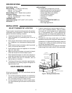
6. Fasten subbase loosely to wall, as shown, using two
mounting screws. Place a level against bottom of
subbase, adjust until level, and then tighten mounting
screws to secure subbase. If holes in wall are too
large and do not allow you to tighten subbase snugly,
use plastic expansion plugs to secure subbase.
SPECIAL SYSTEM CONFIGURATIONS
Electric Heat Furnaces (Single Transformer Systems
Only)
The subbase as shipped may not operate the fan cor-
rectly. If both the heating and cooling system must oper-
ate the fan relay, remove the yellow factory-installed
jumper wire from the Y terminal and connect it to the A
terminal. The fan should now cycle when the thermostat
calls for either heat or cool.
Two-Transformer Systems
If two transformers are used, they MUST be in
phase. Failure to do so may result in personal
injury and/or property damage.
Wire color DOES NOT indicate polarity. Polarity is ob-
tained from an oscilloscope or voltmeter.
Heat Pump Applications
This subbase WILL NOT provide multi-stage heating or
cooling operation. For single-stage heat pump applica-
tions, install a short jumper wire across terminals W and
Y. If the old thermostat has a terminal that is continuously
energized, disconnect the wire from the old thermostat's
terminal and connect it either to the: 1) B terminal, if the
reversing valve is energized on a call for heat; or to the 2)
O terminal, if the reversing valve is energized on a call for
cool. If the system heats on a call for cool, or vice versa,
this wire has been connected to the wrong terminal.
RH and RC must be jumpered for single transformer heat
pump systems.
Special Application Terminals
The B and O terminals can provide switching for special
functions other than heat pump operation. When the
system switch is in the HEAT position, the B terminal is
energized. When the system switch is in the COOL
position, the O terminal is energized.
ATTACH THERMOSTAT TO SUBBASE
1. Remove cover from thermostat base by gripping the
base in one hand. Use the other hand to pull gently at
the top or bottom of the cover.
2. Carefully remove the shipping protective packing
from the switch.
3. Attach thermostat base to subbase, being sure that all
captive screws are tightened snugly, since they serve
as electrical connections between thermostat and
subbase (see fig. 7).
4. Snap cover on thermostat and set switches and
temperature lever to desired set point (see OPERA-
TION section).
5. Turn on power to the system.
GRC
Y
W
B
OFF
FAN
AUTO ON
SYSTEM
COOL HEAT
Mounting screw KEEP THIS AREA
CLEAR OF WIRES
Hole
in wall
Mounting screw
Figure 2. Thermostat subbase
ARH
O
NOTE
CAUTION
!
NOTE
CAUTION
!