


12
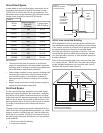
Water System Piping
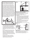
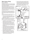
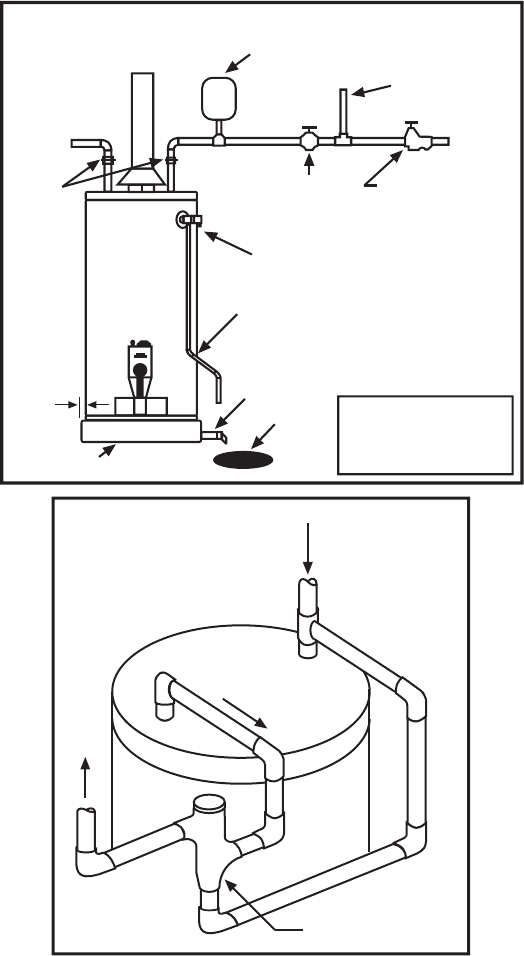
Piping Installation
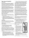
Piping, fittings, and valves should be installed according to
the installation drawing (Figure 13). If the indoor installation
area is subject to freezing temperatures, the water piping
must be protected by insulation.
Water supply pressure should not exceed 80% of the
working pressure of the water heater. The working pressure
is stated on the water heater’s data plate. If this occurs,
a pressure limiting valve with a bypass may need to be
installed in the cold water inlet line. This should be placed
on the supply to the entire house in order to maintain equal
hot and cold water pressures.
IMPORTANT: Heat cannot be applied to the water fittings
on the heater as they may contain nonmetallic parts. If
solder connections are used, solder the pipe to the adapter
before attaching the adapter to the hot and cold water
fittings.
IMPORTANT: Always use a good grade of joint compound
and be certain that all fittings are drawn up tight.
1. Install the water piping and fittings as shown in Figure
13. Connect the cold water supply (3/4” NPT) to the
fitting marked “C”. Connect the hot water supply (3/4”
NPT) to the fitting marked “H”.
IMPORTANT: Some models may contain energy saving
heat traps to prevent the circulation of hot water within the
pipes. Do not remove the inserts within the heat traps.
2. The installation of unions in both the hot and cold water
supply lines is recommended for ease of removing the
water heater for service or replacement.
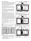
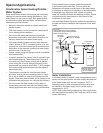
3. The manufacturer of this water heater recommends
installing a tempering valve or an anti-scald device
in the domestic hot water line as shown in Figure 14.
These valves reduce the point-of-use temperature of
the water by mixing cold and hot water and are readily
available for use.
4. If installing the water heater in a closed water system,
install an expansion tank in the cold water line as
specified under Closed System/Thermal Expansion.
5. Install a shut-off valve in the cold water inlet line. It
should be located close to the water heater and be
easily accessible. Know the location of this valve and
how to shut off the water to the heater.
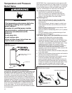
6. A temperature and pressure relief valve must be
installed in the opening marked “Temperature and
Pressure (T & P) Relief Valve” on the water heater.
A discharge line must be added to the opening of
the T&P Relief Valve. Follow the instructions under
Temperature and Pressure Relief Valve.
7. After piping has been properly connected to the water
heater, remove the aerator at the nearest hot water
faucet. Open the hot water faucet and allow the tank to
completely fill with water. To purge the lines of any ex-
cess air, keep the hot water faucet open for 3 minutes
after a constant flow of water is obtained. Close the
faucet and check all connections for leaks.
In a closed system use a
thermal expansion tank
Figure 13
Water Piping Installation
Main
Water
Supply
Cold Water
Inlet Valve
Cold Water
Supply to Fixtures
Hot Water
Outlet
Union
Temperature and
Pressure Relief Valve
Discharge line
6” maximum
above drain
Drain line
3/4” ID
minimum
Drain
Metal
Drain Pan
1 3/4” depth maximum
1”minimum
Massachusetts:
Install a vacuum relief
in cold water line per
section 19 MGL 142.
Pressure reducing
valve with bypass
Figure 14
Typical Tempering
Valve Installation
Follow the tempering
valve manufacturer’s
instructions.
Cold
Water
Inlet
Hot
Water
Outlet
Tempered water
to fixtures
Tempering valve
(Set to 120°F)