


Warning: This fixture is for indoor use only.
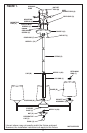
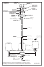
1. Raise shade (R) up to socket assembly (S) and secure with retaining ring (T).
NOTE: if retaining ring(s) (T) was preinstalled, remove before installing glass shade(s) (R).
2. Install lamp(s). Do not exceed recommended wattage.
3. Thread hex nut (X) onto nipple 3 (G3), then thread nipple 3 (G3) into lower fixture
base (Y). Place decorative cap (V) over nipple 3 (G2) and secure with finial (U).
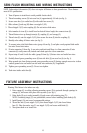
4. Turn power back on at circuit box.
NOTE: Underwriters Laboratories (UL) does not require all fixtures to have ground wires. These fix-
tures meet all UL specifications.
1. Turn off power at circuit box to avoid possible electric shock.
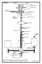
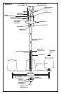
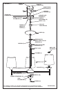
2. Secure mounting bar (A) to outlet box (B) with outlet box screws (C) (not included)
(see fig. 1).
3. Thread hex nut (D) onto nipple 1 (G1) approximately 1/4 inch and insert lock washer (F),
then thread nipple 1 (G1) onto mounting bar (A) and secure with hex nut (D).
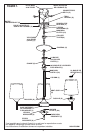
4.
Slide column (J) down over nipple 2 (G2).
5.
Thread nipple 2 (G2) onto couplng (H) (carefully twist loop (I) to secure nipple 2 (G2) if
needed). Do not twist or kink wires
.
6. Open one link on bottom end of chain (K). Attach to loop (I). Securely close link on
chain (K).
7. Thread screw collar ring (L) onto screw collar (M), then place canopy (N) over top of screw
collar (M).
8. Lace wires up through every other link on chain (K) then through screw collar (M) and
nipple 1 (E1).
9. Open one link on top end of chain (K). Attach to loop on screw collar (M). Securely close
link on chain (K).
10. Identify color coding of fixture wires (see fig. 2).
11. To connect wires, take black fixture wire (group A from fig. 3) and place evenly against
black outlet box wire. Do not twist wires.
12. Fit wire connector (O from fig. 1) over wires and twist until there is a firm connection. If
wire connector (O) easily comes off, reattach and check again for a firm connection.
13. Repeat steps 11 and 12 with the white (group B from fig. 3) fixture wires and outlet box
wires.
14. Partially thread green grounding screw (P) into side hole (Q) on mounting bar (A)
15. Wrap ground wire from fixture around green grounding screw (P), leaving enough excess
wire to then connect ground wire and outlet box wire with wire connector (O), if applicable.
16. Tighten green grounding screw (P). Do not over tighten.
17. Tuck wires inside outlet box (B).
18. Remove screw collar ring (L) from screw collar (M).
19. Secure screw collar (M) to nipple 1 (E1).
20. Raise canopy (N) to ceiling and thread screw collar ring (L) to screw collar (M) and tighten
as necessary.
CHANDELIER MOUNTING AND WIRING INSTRUCTIONS
FIXTURE ASSEMBLY INSTRUCTIONS
4