


6104BAFG R06 Page 7
Inspect/Prepare Installation Site
Combustion air supply
The burner cannot properly burn the fuel if it is not
supplied with a reliable combustion air source.
Follow the guidelines in the latest editions of the
NFPA 31 and CSA-B139 regarding providing ad-
equate air for combustion and ventilation.
y
y
Failure to provide adequate air supply could
seriously affect the burner performance and re-
sult in damage to the equipment, asphyxiation,
explosion or fi re hazards.
WARNING
!
Adequate Combustion
and Ventilation Air Supply
Required
Do not attempt to install outside air piping to
the burner without using the outside air kit and
instructions.
y
Failure to comply could result in impaired com-
bustion, appliance soot-up, puffback of smoke,
and fi re or asphyxiation hazards.
Follow the Outside Air Kit
Instructions Exactly
WARNING
!
When retrofi tting appliances that have unlined
stainless steel combustion chambers, protect
the chamber by lining the inside surfaces with a
ceramic fi ber blanket, such as a wet-pac or other
suitable refractory material.
Some steel chambers may not require liners
because the appliance was designed and tested
for use with fl ame retention burners. Refer to the
manufacturer’s instructions.
y
y
Failure to comply could result in damage to the
heating equipment and result in fi re or asphyxi-
ation hazards.
WARNING
!
Protect Steel Combustion
Chamber From Burnout
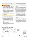
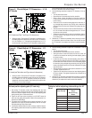
Appliance located in confi ned space
The confi ned space should have two (2) permanent
openings: one near the top of the enclosure and
one near the bottom of the enclosure. Each open-
ing shall have a free area of not less than (1) one
square inch per 1,000 BTU’s per hour of the total
input rating of all appliances within the enclosure.
The openings shall have free access to the build-
ing interior, which should have adequate infi ltration
from the outside.
Exhaust fans and other air-using devices
Size air openings large enough to allow for all air-
using devices in addition to the minimum area re-
quired for combustion air. If there is any possibility
of the equipment room developing negative pres-
sure (because of exhaust fans or clothes dryers, for
example), either pipe combustion air directly to the
burner or provide a sealed enclosure for the burner
and supply it with its own combustion air supply.
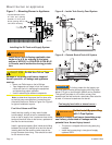
Direct air supply and sidewall venting
Some AFG burners are equipped with combus-
tion air boots to allow use of outside air for com-
bustion.
When sidewall venting appliances, carefully fol-
low appliance and power venter instructions for
installation and wiring.
y
y
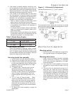
Outside air kit applications
Refer to separate instruction sheet supplied with
AF/AFG outside air kit for installation. This optional
kit allows combustion air to be piped directly to the
burner (Beckett part number 51747).
Clearances to burner and appliance
Provide space around burner and appliance for
easy service and maintenance.
Check minimum clearances against those shown
by the appliance manufacturer and by applicable
building codes.
y
y
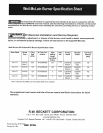
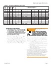
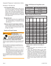
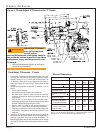
Combustion chamber — Burner retrof t-
ting
Verify that the appliance combustion chamber pro-
vides at least the minimum dimensions given in
Table 3.
Chamber Dimensions (inches)
Firing Rate
(GPH)
Round
I.D.
Rectangular Height Floor to
nozzle
Width Length
0.50 8 7 8 12 5-6
0.75 9 8 9 12 5-6
1.00 10 9 10 12.5 5-6
1.25 11 10 11 12.5 5-6
1.50 12 11 12 13 6-7
2.00 14 12 15 13.5 6-7
2.50 16 13 17 14 7-8
3.00 18 14 18 15 7-8
Table 3. Chamber Dimensions