


6104BAFG R06 Page 13
Disconnect electrical power before installing or
servicing the burner.
Provide ground wiring to the burner, metal con-
trol enclosures and accessories. (This may also
be required to aid proper control system opera-
tion.)
Perform all wiring in compliance with the Na-
tional Electrical Code ANSI/NFPA 70 (Canada
CSA C22.1)
y
y
y
Electrical shock can cause severe
personal injury or death.
WARNING
!
Electrical Shock Hazard
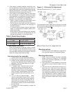
The burner may be equipped with a single-stage
fuel unit for these installations. Connect the fuel
supply to the burner with a single supply line if you
want a one-pipe system (making sure the bypass
plug is NOT installed in the fuel unit.) Manual bleed-
ing of the fuel unit is required on initial start-up. If
connecting a two-pipe fuel supply, install the fuel
unit bypass plug.
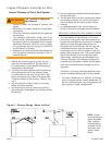
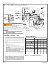
Fuel supply below the level of the burner –
When the fuel supply is more than eight feet below
the level of the burner, a two-pipe fuel supply sys-
tem is required. Depending on the fuel line diam-
eter and horizontal and vertical length, the instal-
lation may also require a two-stage pump. Consult
the fuel unit manufacturer’s literature, included with
the burner, for lift and vacuum capability.
Fuel line installation –
Continuous lengths of heavy wall copper tubing
are recommended. Always use f are f ttings.
Never use compression f ttings.
Always install fi ttings in accessible locations.
Proper routing of fuel lines is required to prevent
air cavitation and vibration.
y
y
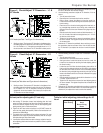
The oil supply inlet pressure to the burner can-
not exceed 3 psig.
Insure that a pressure limiting device is installed
in accordance with the latest edition of NFPA 31.
Do NOT install valves in the return line.
(NFPA 31, Chapter 8.)
Gravity Feed Systems: Always install an anti-
siphon valve in the oil supply line or a solenoid
valve (RWB Part # 2182602U) in the pump/noz-
zle discharge tubing to provide backup oil fl ow
cut-off protection.
y
y
y
y
Damage to the fi lter or pump seals could cause
oil leakage and a fi re hazard.
Oil Supply Pressure
Control Required
!!
CAUTION
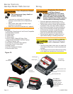
Wire burner
Burner packaged with appliance
Refer to appliance manufacturer’s wiring diagram
for electrical connections.
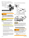
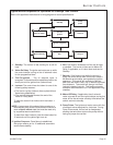
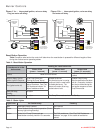
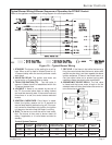
Burner installed at jobsite
Refer to Figures 11a and 11b, for typical burner
wiring, showing cad cell primary controls. Burner
wiring may vary, depending on primary control
actually used.
Refer to the appliance manufacturer’s wiring dia-
gram prior to connecting the burner wiring. All wir-
ing must be in accordance with the latest revision
of National Electric Code NFPA 70 and all local
codes and regulations. In Canada, all wiring is
to be in accordance with the Canadian Electrical
Code, Part 1.
The 7505 primary control with valve-on delay (pre-
time) and burner motor-off delay (post-time) re-
quires a constant 120 volts AC power source sup-
plied to the BLACK wire on the control. The RED
wire goes to the appliance limit circuit. Please note
that other control manufacturers may use different
wire colors for power and limit connections.
Special wiring required with covered
burners
The mounting plate is not a conduit connec-
tion point. Pass conduit and attached connector
through the opening in the mounting plate and at-
tach it directly to the burner-mounted 4x4 electrical
box.
If attaching a burner cover to a previously installed
burner, attach the mounting plate and then slide the
conduit into the “J” shaped conduit slot.
y
y
y
Wire burner
If the residence is unattended in severely cold
weather, burner primary control safety lockout,
heating system component failures, power
outages or other electrical system failures
could result in frozen plumbing and water
damage in a matter of hours. For protection,
take preventive actions such as having a
security system installed that operates during
power outages, senses low temperature and
initiates an effective action. Consult with your
heating contractor or a home security agency.
Frozen Plumbing and
Water Damage Hazard