


3398
5
GB
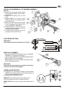
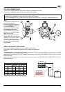
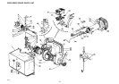
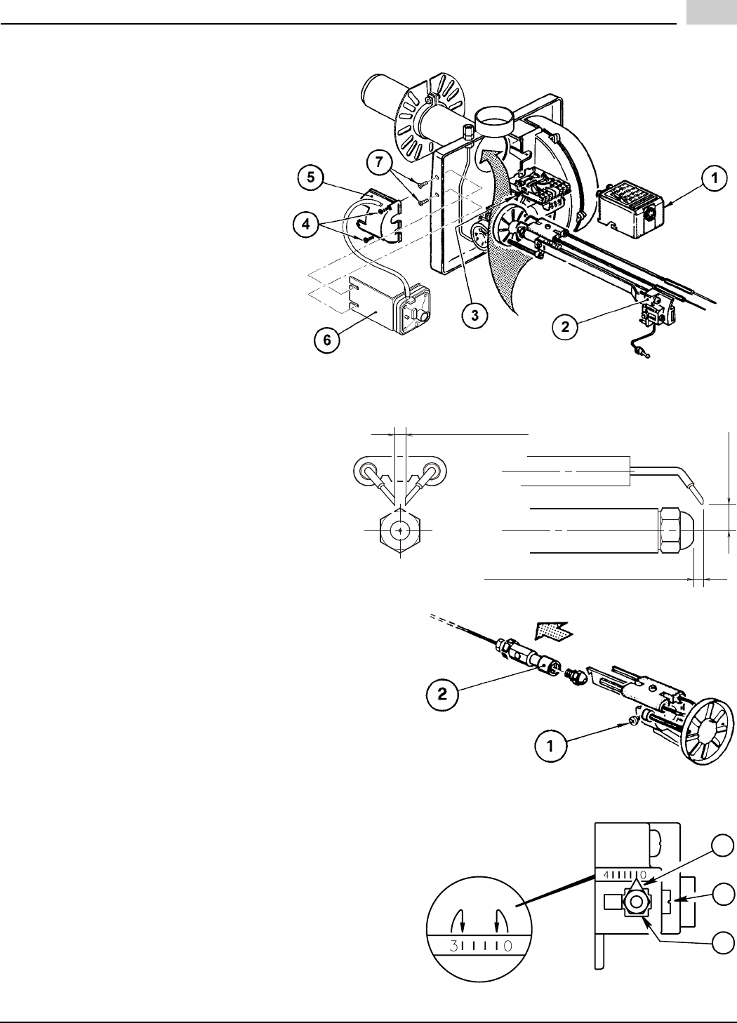
INSTALLATION/REMOVAL OF DRAWER ASSEMBLY
Removal:
A) Remove the air pressure switch support
(6) from the front shield by the two retain-
ing screws (7)
B) Loosen off oil delivery tube nut from
pump.
C) Loosen SCREW (3), and then unplug
CONTROL BOX (1) by carefully pulling it
back and then up.
D) Remove the AIR TUBE COVER PLATE
(5) by loosening the retaining SCREW
(4) (Two SCREWS – Model BF5).
E) Loosen SCREW (2), and then slide the
complete drawer assembly out of the
combustion head as shown.
F) To insert drawer assembly, reverse the
procedure in items A to E above.
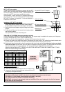
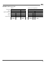
ELECTRODE SETTING
IMPORTANT:
These dimensions must be observed and verified.
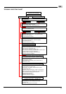
NOZZLE PLACEMENT
- Remove the NOZZLE ADAPTER (2) from the DRAWER
ASSEMBLY by loosening the SCREW (1).
- Insert the proper NOZZLE into the NOZZLE ADAPTER and
tighten securely (Do not over tighten).
- Replace adapter, with nozzle installed, into drawer assem-
bly and secure with screw (1).
IMPORTANT:
The nozzle and the pump pressure must be in accordance
with the burner setup chart at page 9.
TURBULATOR SETTING
A) Loosen NUT (1), and then turn SCREW (2) until the INDEX
MARKER (3) is aligned with the correct index number as
per the burner setup chart at page 9.
B) Retighten the RETAINING NUT (1).
MODEL BF3: Zero and three are scale indicators only.
From left to right the first line is 3 and the last line 0.
MODEL BF5: Same as above, except scale indicators are 0
and 4.
E9327
5/32” or 4 mm
5/32” to 13/64” or 4 to 5 mm
13/64”
5 mm
D6003
S7459
3
2
1
D7520