3398
3
GB
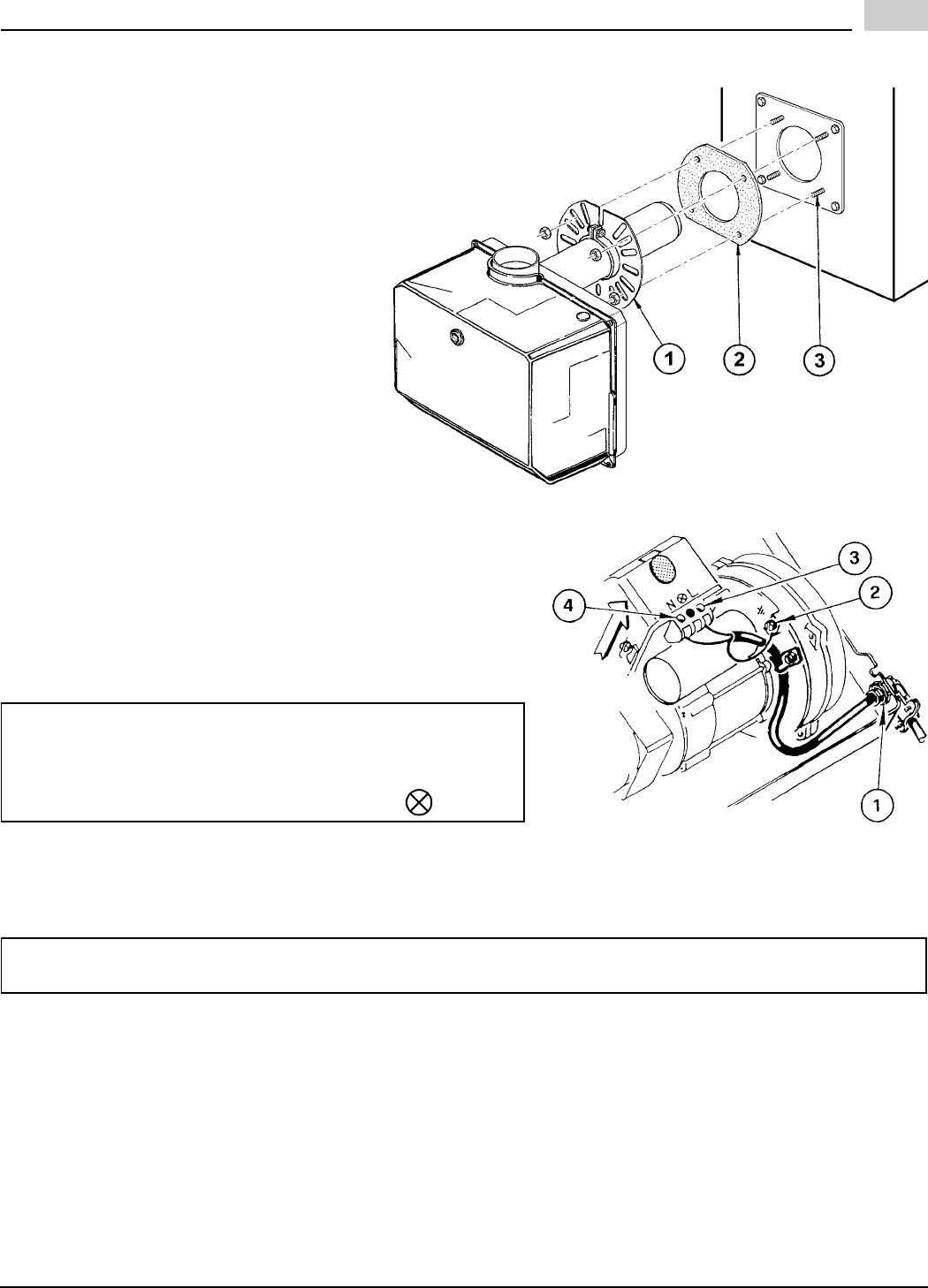
MOUNTING THE BURNER TO THE BOILER
- Position the MOUNTING GASKET (2) be-
tween the flat surface of the UNIVERSAL
MOUNTING FLANGE (1) installed on the
burner and the appliance.
- Line up the holes in the UNIVERSAL
MOUNTING FLANGE with the STUDS
(3) on the appliance mounting plate and
securely bolt the UNIVERSAL MOUNT-
ING FLANGE to the plate.
To remove the burner from the boiler, re-
verse the procedure.
ELECTRICAL CONNECTIONS
It is advisable to leave the control box off the sub-base while com-
pleting the electrical connection to the burner.
1) Wire access hole (Use BX electrical connector)
2) Earth ground conductor terminal (Green wire)
3) Hot conductor terminal (Black wire)
4) Neutral conductor terminal (White wire)
Using the appropriate diagram below, make electrical connec-
tions to burner.
All wiring must be done in accordance with existing electrical codes, both national and local.
When all electrical connections have been made, the control box may be put back in place on the sub-base.
E9328
D7954
WARNING:
The hot (black) wire must be connected to the L terminal and the
neutral (white) wire must be connected to the N terminal or the
primary safety control will be damaged.
Do not connect wither wire to the terminal marked
.
WARNING: DO NOT activate burner until proper oil line connections have been made, or failure of the
pump shaft seal may occur.


