


3223
10
GB
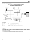
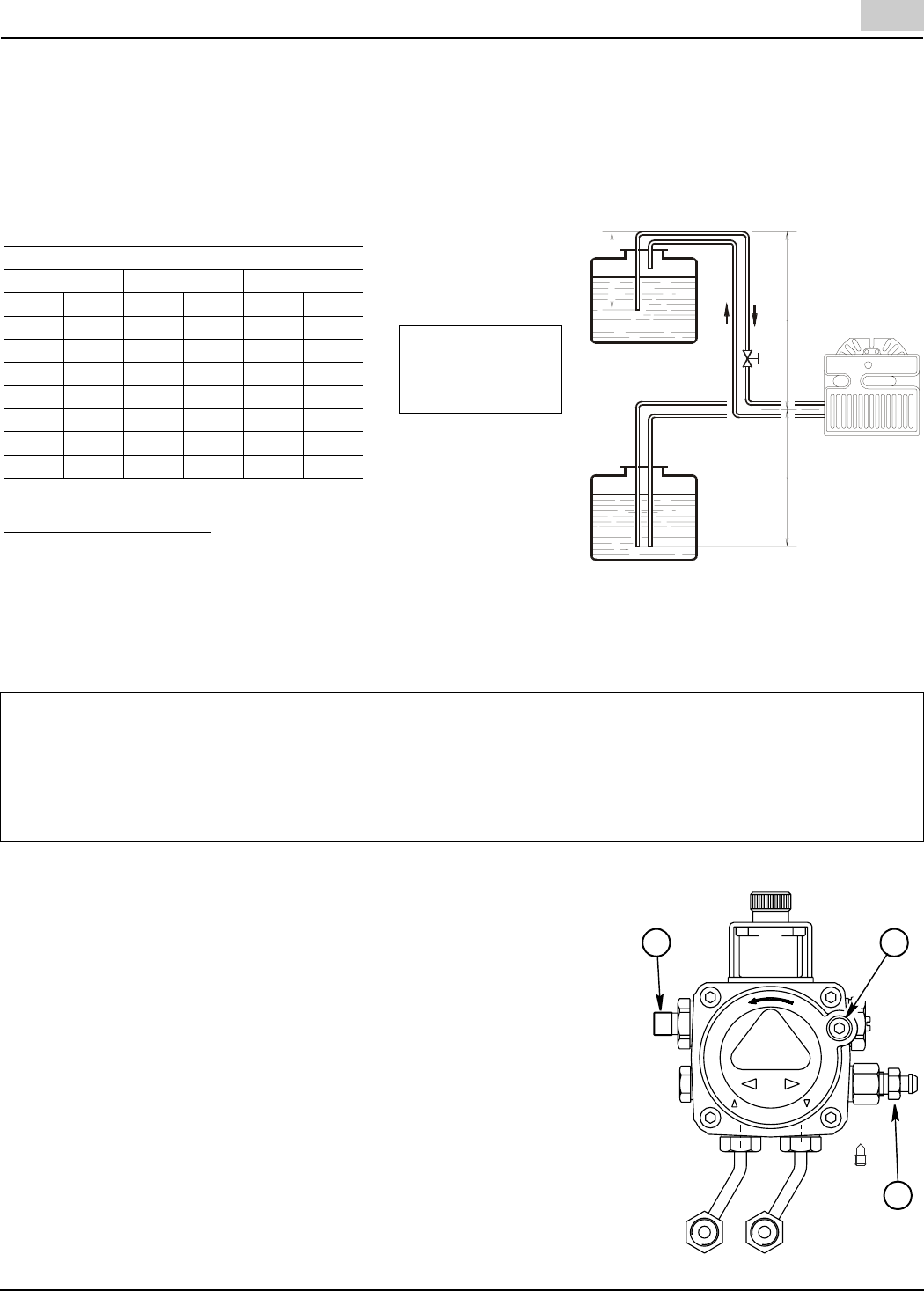
TWO LINE (LIFT SYSTEM)
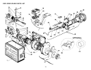
A) If a two-line system is required, install the By-pass plug provided. The by-pass plug is installed in the return port
of the pump. A 2.5-mm hexagonal key provided with the by-pass plug is to be used to install the plug.
DO NOT use an inch size hexagonal key; damage to the by-pass plug may result.
When operating on a two-line system, supply and return lines should be the same diameter and both should
extend to the same depth inside the fuel tank. Be sure there are no air leaks or blockages in the piping sys-
tem. Any obstructions in the return line will cause failure of the pump shaft seal.
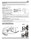
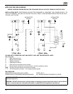
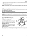
PUMP PURGE
NOTE: To protect the pump gears, it is advisable to lubricate the pump prior
to purging a lift system. Apply oil through the VACUUM PORT (C).
A) SINGLE LINE (GRAVITY FEED SYSTEM)
I. Loosen the bleeder valve (A) until oil flows out. Tighten the bleeder valve
securely and startburner.
II. When bleeding the pump by pressure:
1) Loosen the bleeder valve (A).
2) Disconnect nozzle oil supply line at the pump nozzleport (B).
3) Attach a flexible plastic tube to the pump nozzle, port directing the oil
flow into a bucket.
4) Loosen the screw(s) securing the air tube cover, allowing it to be re-
moved freely.
5) Holding the air tube cover in its proper location start the burner.
6) When the solenoid valve is engaged approximately 10 seconds after
starting, remove the air tube cover and shine a light source on the
photocell, allowing it to see false light.
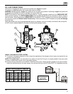
WARNING:
- Pipe dope or Teflon tapes are NOT to be used on any direct oil connection to the fuel pump.
- The height ‘P’ in Pipe Length Charts should not exceed 13 feet (4 m).
- The vacuum should not exceed 11.44 inches of mercury.
IMPORTANT:
An external, appropriately listed and certified oil filter must be placed in the fuel line between the fuel tank
and the burner pump.
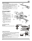
To install the by-pass plug:
1) Remove the return plug (7).
2) Install the by-pass plug (4) using the 2.5 mm hexagonal key.
B) Attach the two PIPE CONNECTORS (6) to the pump SUPPLY and pump RETURN PORTS (5 and 7). Attach the
required piping to these two pipe connectors using the NPT/ METRIC ADAPTERS that are supplied with the burner.
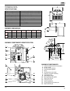
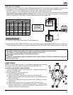
2 LINE (LIFT) SYSTEM-PIPE LENGTHS
H 3/8” OD 1/2” OD
FT M FT M FT M
0.00.011535330100
1.50.510030330100
3.0 1.0 80 25 330 100
5.0 1.5 65 20 295 90
6.5 2.0 50 15 230 70
9.5 3.0 25 8 100 30
11 3.5 20 6 65 20
ATTENTION:
do not exceed
pipe lengths
indicated in chart!
D6008
H
P
H
D7284
C
A
B