


3223
8
GB
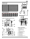
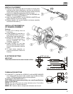
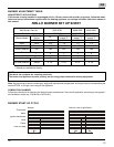
NOZZLE PLACEMENT
A) Determine the proper firing rate for the boiler or furnace units,
considering the specific application, and then use the Burner
Setup charts on page 12 to select the proper nozzle and pump
pressure to obtain the required input from the burner.
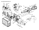
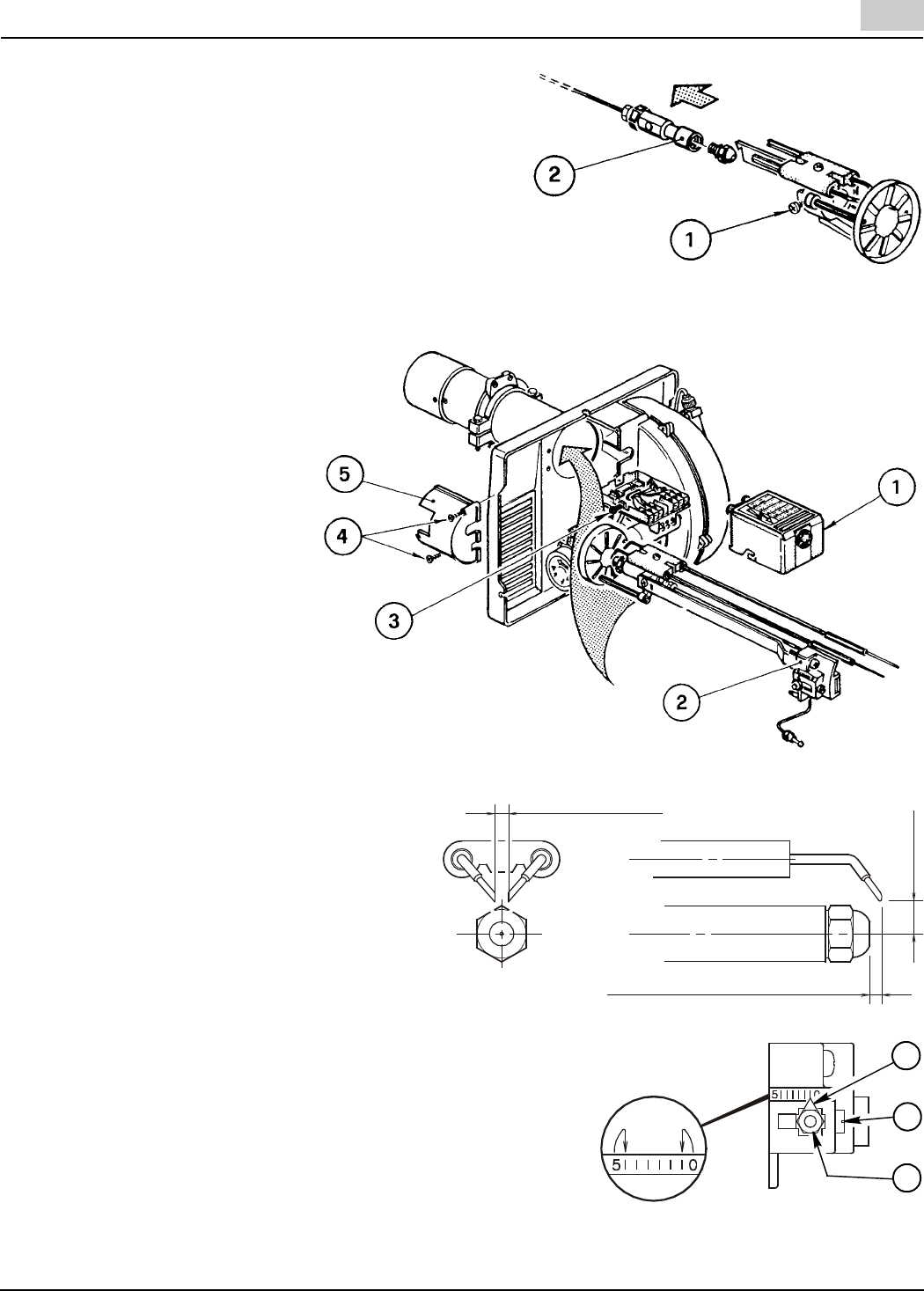
B) Remove the NOZZLE ADAPTER (2) from the DRAWER AS-
SEMBLY by loosening the SCREW (1).
C) Insert the proper NOZZLE into the NOZZLE ADAPTER and
tighten securely (Do not over tighten).
D) Replace adapter, with nozzle installed, into drawer assembly
and secure with screw (1).
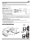
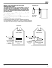
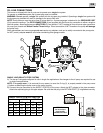
INSTALLATION/REMOVAL
OF DRAWER ASSEMBLY
Removal:
A) Loosen off oil delivery tube nut
from pump.
B) Loosen SCREW (3), and then un-
plug CONTROL BOX (1) by care-
fully pulling it back and then up.
C) Remove the AIR TUBE COVER
PLATE (5) by loosening the re-
taining SCREW (4) (Two
SCREWS – Model F5).
D) Loosen SCREW (2), and then
slide the complete drawer assem-
bly out of the combustion head as
shown.
E) To insert drawer assembly, re-
verse the procedure in items A to
D above.
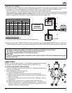
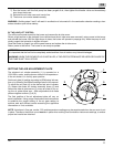
ELECTRODE SETTING
IMPORTANT:
These dimensions must be observed and verified.
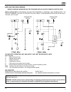
TURBULATOR SETTING
A) Loosen NUT (1), and then turn SCREW (2) until the INDEX MARKER
(3) is aligned with the correct index number as per the Burner Setup
charts, or OEM specifications given with the appliance.
B) Retighten the RETAINING NUT (1).
NOTE: OEM specifications take priority over retrofit specifications
shown in this manual.
MODEL F3: Zero and three are scale indicators only. From left to
right the first line is 3 and the last line 0.
MODEL F5: Same as above, except scale indicators are 0 and 4.
S7459
S7460
5/32” or 4 mm
5/32” to 13/64” or 4 to 5 mm
13/64”
5 mm
D6003
3
2
1
D5997