


Part Number 550-141-816/07988
LGB-6 to LGB-20 Series 2 – Control Supplement
1. Operating control begins startup sequence.
a. Limit control contacts are closed.
2. Pilot proving module energized.
a. Pilot solenoid opens.
b. Pilot ignition spark begins.
c. Pilot ignites.
d. Pilot proves.
3. Main flame proving module energized from pilot proving module.
a. Secondary gas valve opens.
b. Main gas valve opens to low fire position.
c. Main burners ignite at low fire.
d. Main flame sensor proves low fire carryover.
e. Main gas valve opens to high fire position.
f. Main burners increase to high fire.
4. For dual base assembly - operating control energizes controls for each base assembly at the
same time. See steps 1 through 3 above.
5. Boiler shuts down when operating control satisfied.
Sequence of operation
On failure to sense pilot flame, the pilot-proving module will wait 5
minutes, then retry for ignition. Upon 2 consecutive pilot flame failures,
the control will lockout and illuminate the red lockout light.
If the boiler locks out, the alarm contacts on the terminal strip (terminals
A1 and A2) close. These contacts are rated to 15 amps, 250 V. To reset the
boiler, push the red lockout button.
V
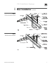
Wiring – continued
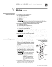
1. Determine right or left electrical supply wiring.
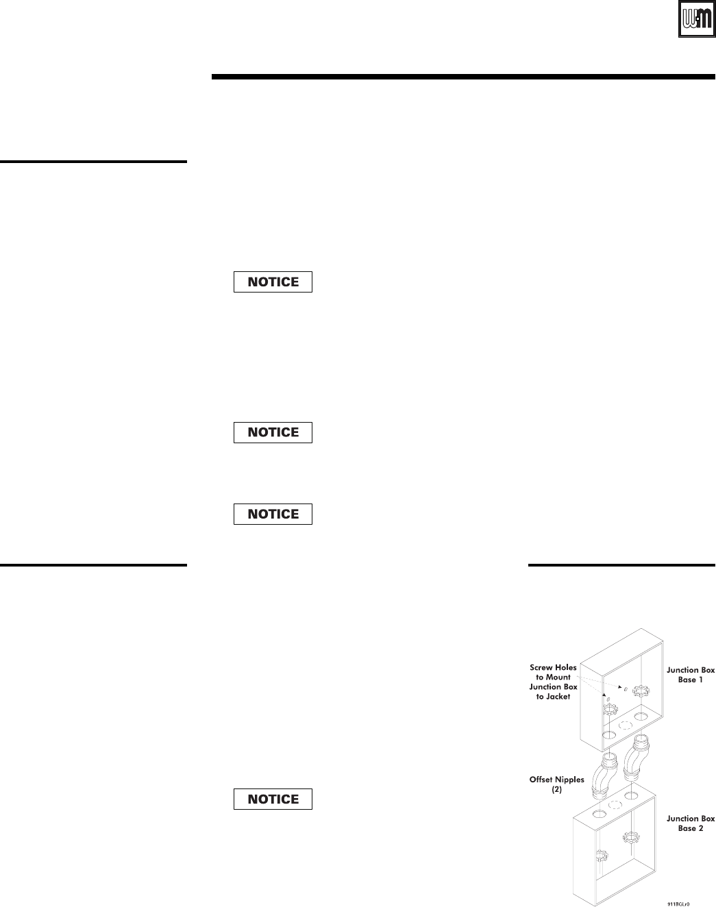
2. Attach electrical junction box(es) to inside jacket end
panel. Screws and nuts are provided. For dual base
boilers, use offset nipples (provided) to connect
junction boxes together (as at right), then hang
junction boxes by screwing top box to boiler jacket.
See Figure 4.
3. Attach control transformer(s) to junction box(es).
4. Drill 1/8” hole in interior jacket panel midway between
ignition control panel and left jacket panel. Mount
wire support clip using sheet metal screw (furnished).
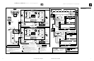
5. Complete wiring per diagrams, Figure 3 (pages 6
and 7) and Figure 5 (page 9). Terminate at secondary
gas valve in valve junction box with wirenuts and
strain relief provided.
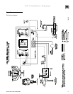
6. Install pilot proving and main flame proving ground
connections as shown in Figures 1 and 2 and wiring
diagram. Route wires through wire support clip.
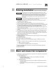
Wiring procedure
“Hot” side of line voltage to boiler
must be wired directly to limit
circuit, then fed to transformer
primary(ies).
Dual Base: “R” terminal of
secondaries are to supply power
to bases independently of each
other. Do not wire “R” terminals
together.
Figure 4
Junction box assembly
dual base boilers
On failure to sense main flame, the main flame-proving module will
lockout and illuminate the red lockout light.