


Part Number 550-141-816/0798 5
CSD-1 Control System – Propane gas
IV Gas piping
1. Contact gas supplier to size pipes, tanks and regulator.
a. Inlet gas pressure to manual main shut-off gas valve —
minimum 11” W.C., maximum 13” W.C.
b. If pressure to gas valve exceeds 13” W.C., install 100% lock-up gas pressure regulator
upstream of hand valve.
2. Remove gas supply knockout disc from jacket panel.
3. Follow good piping practices.
4. Pipe joint compound (pipe dope) must be resistant to corrosive action of liquefied
petroleum gases. Apply sparingly only to male threads of pipe joints.
5. Install drip leg at inlet of gas connection to boiler. Where local utility requires, extend drip
leg to floor.
6. Install ground joint union when required for servicing.
7. Support piping by hangers, not by boiler or its accessories.
8. Purge all air from supply piping.
9. Before operating boiler, check boiler and its gas connections for leaks.
a. Close manual main shut-off valve during any pressure testing at less than 13” W.C.
b. Disconnect boiler and gas valve from gas supply piping during any pressure test
greater than 13” W.C.
Do not check for gas leaks with an open flame – BUBBLE TEST. Failure to
use bubble test or test for leaks can cause severe personal injury, death or
substantial property damage.
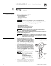
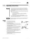
1. All wiring must be installed in accordance with the requirements of the National Electrical
Code and any additional national, state or local code requirements having jurisdiction. All
wiring must be N.E.C. Class 1.
2. The boiler must be electrically grounded in accordance with the National Electrical Code,
ANSI/NFPA No. 70-latest edition. Use 105 °C. thermoplastic wire, or equivalent, if any of
the original wire must be replaced (except for pilot spark, sense and ground wires).
3. Supply wiring to the boiler must be No. 14 gauge or heavier. Install in conduit.
4. A separate electrical circuit with a fused disconnect switch (15 amp. recommended) should
be used for the boiler.
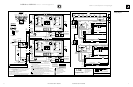
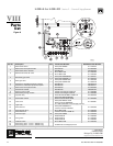
5. Refer to wiring diagrams, Figure 3 (pages 6 and 7) and Figure 5 (page 9). See section,
“Wiring procedure” on page 8.
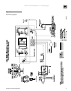
6. Figure 5 on page 9 is the Field Wiring Diagram. See Figure 3, pages 6 and 7, for the
schematic and ladder wiring diagrams.
For your safety, turn off electrical power supply before making any electrical
connections to avoid possible electrical shock hazard.
V
Wiring