


Part Number 550-141-816/07982
LGB-6 to LGB-20 Series 2 – Control Supplement
I New installation
1. Remove all burners from base box assembly. Remove 3.95 mm natural gas main burner
orifices in manifold. Install 2.40 mm propane gas main burner orifices. Use pipe dope
sparingly only on male ends. Use pipe dope compatible with propane gases. Do not
overtighten orifices.
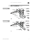
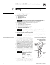
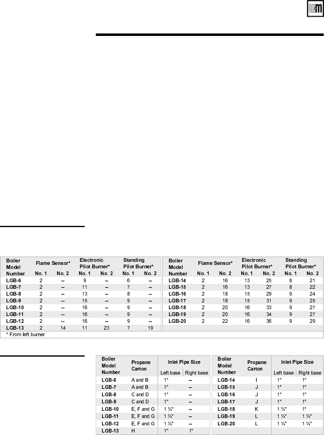
2. Install pilot burners and flame sensor(s). See Figures 1 and 2 (page 3). Follow Table 1,
below for electronic pilot burner (UCS), standing pilot burner (Q327) and flame sensor
locations on manifold.
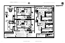
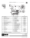
3. Install gas controls and ignition control panel as shown in Table 2, below and Figure 6
(page 12).
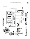
4. Attach pilot switch box to interior jacket panel. See Figure 6 (page 12). Connect
thermocouple from standing pilot to switch box. Cut 60” pilot tubing into 2 pieces to
make connections from pilot valve to pilot switch box and from pilot switch box to
standing pilot.
5. Attach:
a. 550-223-710 label at boiler operating instruction label. Place so that this label reads
first.
b. 550-223-796 label at rating label.
c. Wiring diagram on door (one on each base).
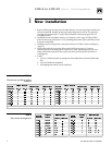
Table 1
Pilot burner and flame sensor
locations
Table 2
Gas control arrangement