


GOLD CGi Gas-Fired Water Boiler — Boiler Manual
48
Part Number 550-110-710/0107
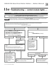
Troubleshooting — components11b
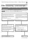
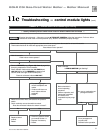
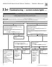
Troubleshooting — procedure11a
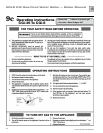
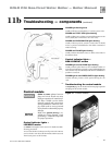
Air pressure switch
Make sure boiler water temperature is 100 °F or cooler
before starting procedure to obtain appropriate read-
ings.
The boiler will not operate correctly unless pressure
switch hoses are correctly located. The red hose con-
nects from the right side (negative) hose barb to the
flue collector. The white hose connects from the left
side (positive) hose barb of the switch to the connector
box (between flue collector and inducer) as shown in
Figure 36, page 49.
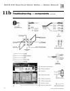
Check pressure switch setting
1. See Figure 36, page 49, and Table 9.
2. Remove both air pressure switch hoses from air pressure switch.
3. Install tees and tubing as shown in
Figure 36, page 49, to inclined manom-
eter.
4. Turn off gas valve and set thermostat to call for heat. Inducer will run but burn
-
ers will not ignite.
5. Check for 24 VAC between both air pressure switch terminals.
Troubleshooting air pressure reading
1. If manometer reading is lower than the setpoint of the switch (see Table 9)
— check for possible causes:
• blockage in hoses
• obstruction in inducer housing outlet
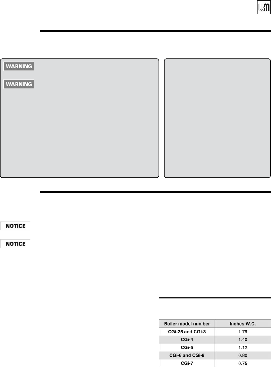
Table 9 Pressure switch setpoint (for elevations
above 2,000 ft, contact your local Weil-
McLain sales office for details.)
• loose inducer wheel on motor shaft
• inducer motor not in proper rpm
• inducer back plate not sealed properly
• blockage in block assembly
6. If manometer reading is above the setpoint of the switch
(see
Table 9), but there is not 24 VAC between both air
pressure switch terminals — replace air pressure switch.
Return to normal operation
When pressure reading is correct and air pressure switch is
operating properly — remove tees and reinstall hoses to air
pressure switch.
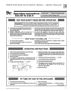
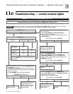
Check the following:
1. Wire connectors to control module are se-
curely plugged in at module and originating
control.
2. Air pressure switch hoses are properly and
securely plugged in and are not damaged.
3. Gas pressures:
a. With boiler off — 13” w.c. maximum
natural or propane gas pressure up
-
stream of gas valve.
b. With boiler on:
• 5” w.c. minimum natural gas
pressure or 11” w.c. propane gas
pressure upstream of gas valve.
• 3 ½” w.c. minimum natural gas
pressure or 10” w.c. propane gas
pressure downstream of gas valve
— Can be adjusted by regulator
on gas valve.
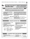
Label all wires prior to disconnection when servicing
controls. Wiring errors can cause improper and danger-
ous operation.
Never jumper (bypass) rollout thermal fuse element
or any other device except for momentary testing as
outlined in Troubleshooting Charts. Severe personal
injury, death or substantial property damage can re-
sult.
Before troubleshooting:
1. Have the following items:
a. Voltmeter that can check 120 VAC and 24 VAC.
b. Microammeter with a minimum scale range of 0-25.
c. Continuity checker.
d. U-tube manometer.
2. Check for 120 VAC (minimum 102 VAC to maximum 132 VAC) to
boiler.
3. Make sure thermostat is calling for heat and contacts (including appro-
priate zone controls) are closed. Check for 24 VAC between thermostat
wire nuts and ground.