


Part Number 550-110-710/0107
31
GOLD CGi Gas-Fired Water Boiler — Boiler Manual
Field wiring6
Thermostat
1. Connect thermostat as shown on wiring diagram
on boiler.
2.
Install on inside wall away from influences of
drafts, hot or cold water pipes, lighting fixtures,
television, sunrays, or fireplaces.
3. If thermostat has a heat anticipator, set heat antici-
pator in thermostat to match power requirements
of equipment connected to it. If connected directly
to boiler, set for 0.1 amps plus gas valve current.
See information on wiring diagram as shown in
Figure 32, page 39. For other devices, refer to
manufacturer’s specifications. Wiring diagram on
boiler gives setting for control module and gas valve.
Also see instructions with thermostat.
Junction Box (furnished)
1. Connect 120 VAC power wiring as shown in
Figure 27.
2. Fused disconnect or service switch (15 amp. recom
-
mended) may be mounted on this box. For those
installations with local codes which prohibit installa-
tion of fused disconnect or service switch on boiler,
install a 2 x 4 cover plate on the boiler junction box
and mount the service switch remotely as required
by the code.
For your safety, turn off electrical power supply at
service entrance panel before making any electrical
connections to avoid possible electric shock hazard.
Failure to do so can cause severe personal injury or
death.
Wiring must be N.E.C. Class 1.
If original rollout thermal fuse element wire as supplied
with boiler must be replaced, use only type 200°C wire
or equivalent. If other original wiring as supplied with
boiler must be replaced, type 105°C wire or equivalent
must be used.
Boiler must be electrically grounded as required by
National Electrical Code ANSI/NFPA 70–latest edi-
tion.
Electrical installation must
comply with:
1. National Electrical Code and any other national,
state, provincial or local codes or regulations.
2. In Canada, CSA C22.1 Canadian Electrical Code
Part 1, and any local codes.
Wiring connections
Boiler is shipped with controls completely wired.
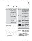
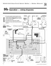
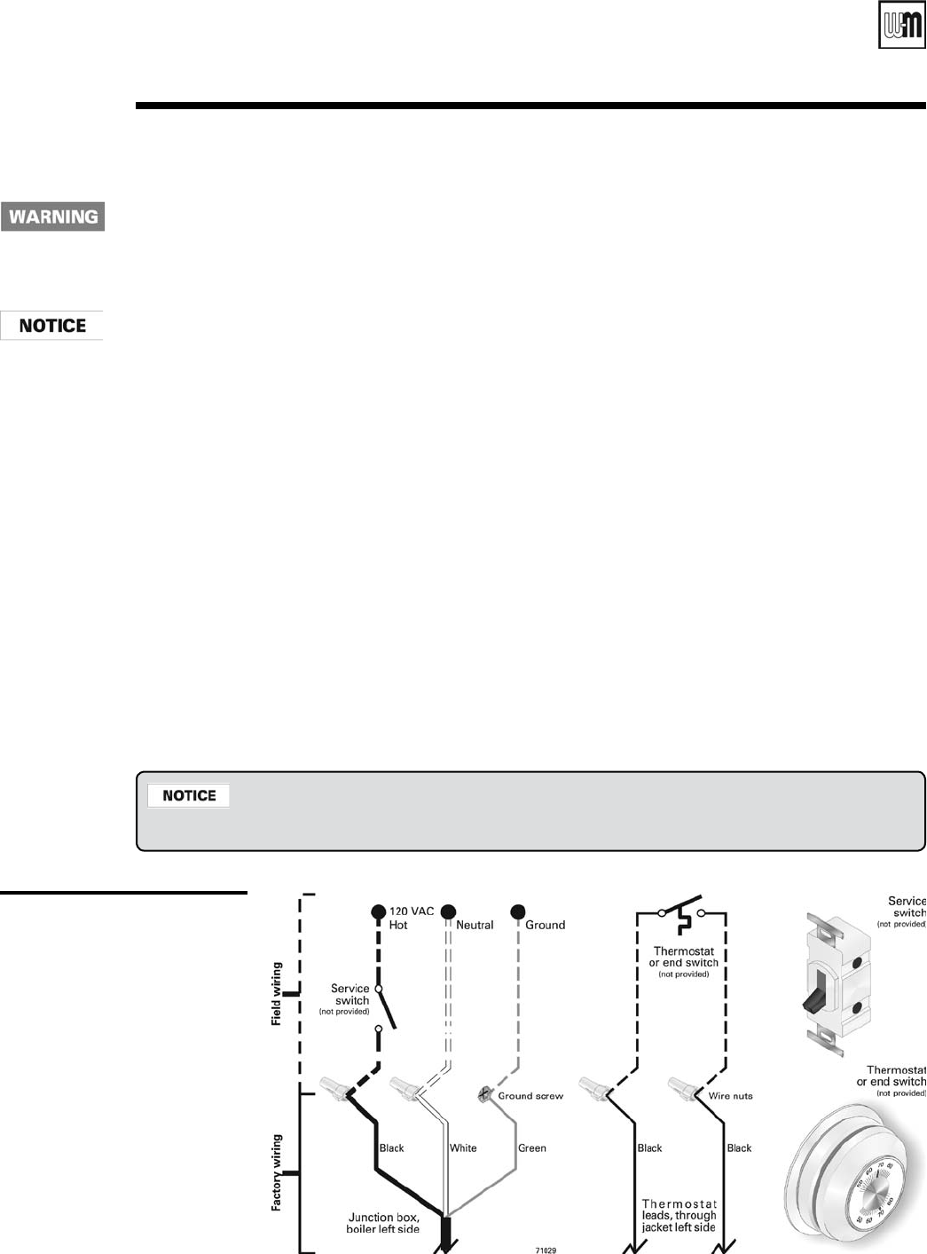
Figure 27
Field wiring connections —
service switch and thermostat
(or end switch)
provided by installer
The CGi control module is polarity-sensitive. The hot and neutral wires must be connected to
the correct leads. A flashing POWER light usually indicates reversed polarity of 120 VAC lead
wires.