


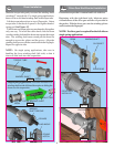
Slide the right hand end bracket over the drive gear. Attach
end bracket and the flagangle to the jamb with (2) 5/16 x
1-5/8” lag screws. (see Fig. 11)
5
OPENER
POWER
HEAD
SPRING PAD
TORQUE TUBE
MOUNTING
STUDS
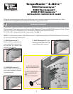
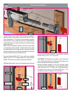
Power Head/
Support Bracket Installation
(2) 2” LAG SCREWS
SUPPORT
BRACKET
MOTOR
(2) 1/4-20 FLANGE NUTS
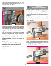
Locate the spring pad. The spring pad is a vertical running
board directly above the door. Remove (2) 1/4-20 flange
nuts from bottom of opener power head. NOTE: Do not
discard flange nuts. Place the support bracket underneath
opener power head, to the right side of motor, centered on
spring pad.
Level the torque tube to the top of the door section with the
idrive™ resting on the support bracket. Once torque tube
is level, secure support bracket to the spring pad with (2)
1/4 x 2" lag screws.
SUPPORT BRACKET
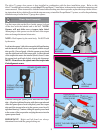
Lift and slide the opener power head over the support
bracket, aligning the mounting studs with the bracket slots.
Loosely fasten to mounting studs with the (2) 1/4-20 flange
nuts. NOTE: Do not tighten 1/4-20 flange nuts to power
head studs at this time.
OPENER POWER HEAD
FIG. 13
FIG. 14
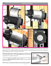
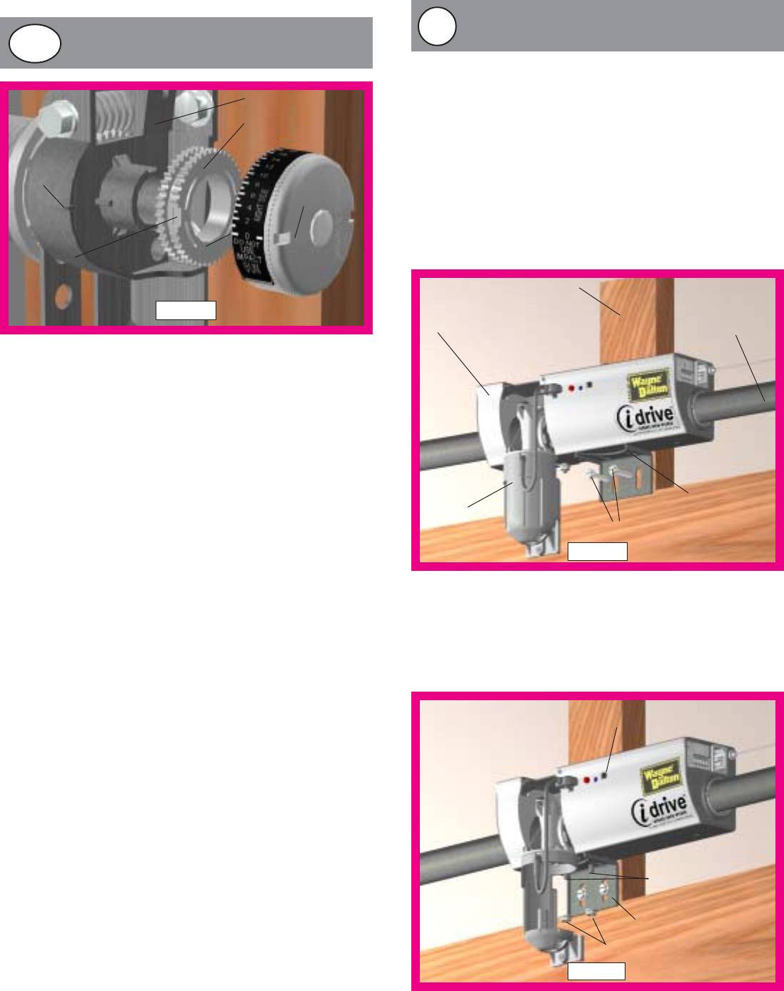
Counter Installation
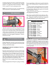
Begining with the right side, install the counter gear with the
missing tooth toward the outside, away from the end bracket.
Press the counter gear onto the end bracket until snaps
engage. Select the right hand counter cover assembly and
align the hex of the counter cam with the end of the winding
shaft. Also, align the “0” on the counter cover with the
raised rib on the end bracket. Press the counter cover
assembly against the counter gear until it locks into place.
Repeat the Drive Gear/End Bracket Installation and
Counter Installation sections for the left hand side
installation.
NOTE: No drive gear, counter gear or counter cover
assembly is required on left hand side for single spring
applications. Only an end bracket is needed.
IMPORTANT! At this time do not wind counter balance
springs!
END BRACKET
COUNTER
GEAR
RIGHT HAND
COUNTER
COVER
ASSEMBLY
“0”
RAISED
RIB
MISSING TOOTH
(TOWARD OUTSIDE)
FIG. 12
14b
15