


®
Follow the corresponding steps in this insert with the steps in the installation manual provided with the door. These
modifications are designed to accommodate the new idrive™ garage door opener.
Top Bracket Installation
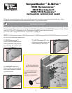
TOP SECTION
RIB
(2) CARRIAGE
BOLTS
TOP
BRACKET
TOP
BRACKET
SLIDE
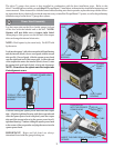
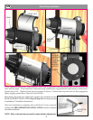
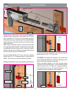
3) 9200/9100 Foamcore™
(below) will have galvanized hard-
ware, with a laminated (soft) back-
ing on the sections.
(4) SELF-TAPPING
SCREWS
2
ND
SET OF HOLES ON
9600 THERMOGARD®
AND
9200/9100 FOAMCORE™
(2) HEX
NUTS
1
ST
SET OF HOLES ON
9900 THERMOWAYNE™
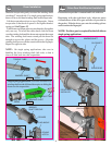
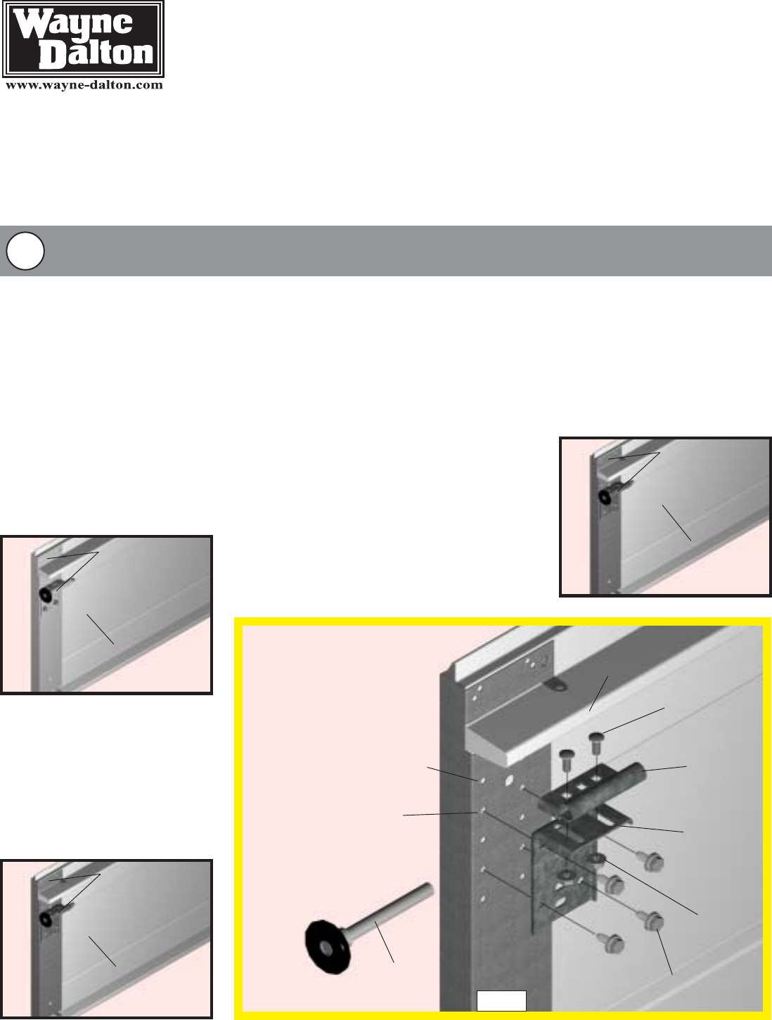
To install the L-shaped top brackets, align the top holes in the top bracket with the first set of holes in the endcap for 9900
Thermowayne™ doors and second set of holes for 9600 Thermogard
®
doors and 9200/9100 Foamcore™ doors. Fasten
using (4) 1/4-20 x 5/8” self tapping screws. Secure the top bracket slide to the bracket using
(2) 1/4-20 x 5/8” carriage bolts and nuts. Insert rollers. (see Fig. 1)
NOTE: To differentiate between a 9900 Thermowayne™, 9600 Thermogard® and 9200/9100 Foamcore™ door mod-
els, look for the following characteristics:
TorqueMaster™ & idrive™
9900 Thermowayne™
9600 Thermogard®
9200/9100 Foamcore™
INSTALLATION INSTRUCTIONS INSERT
ROLLER
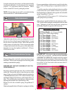
1) 9900 Thermowayne™
(below) will have painted hard-
ware (top brackets, bottom brack-
ets, end caps, etc.) with a steel
backing on the sections.
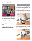
2) 9600 Thermogard® (right)
will have galvanized hardware, with
a steel backing on the sections.
GALVANIZED
HARDWARE
STEEL
BACKING
GALVANIZED
HARDWARE
LAMINATED
(SOFT) BACKING
PAINTED
HARDWARE
STEEL BACKING
FIG. 1
2
8