


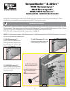
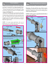
Using the emergency disconnect, pull disconnect handle
downwards and place it in the manual door operated
position. Use disconnect label for reference. Motor
will be rotated 90° from its packaged position.
NOTE: If motor does not pivot 90°, see troubleshooting
section in the idrive™ main installation manual.
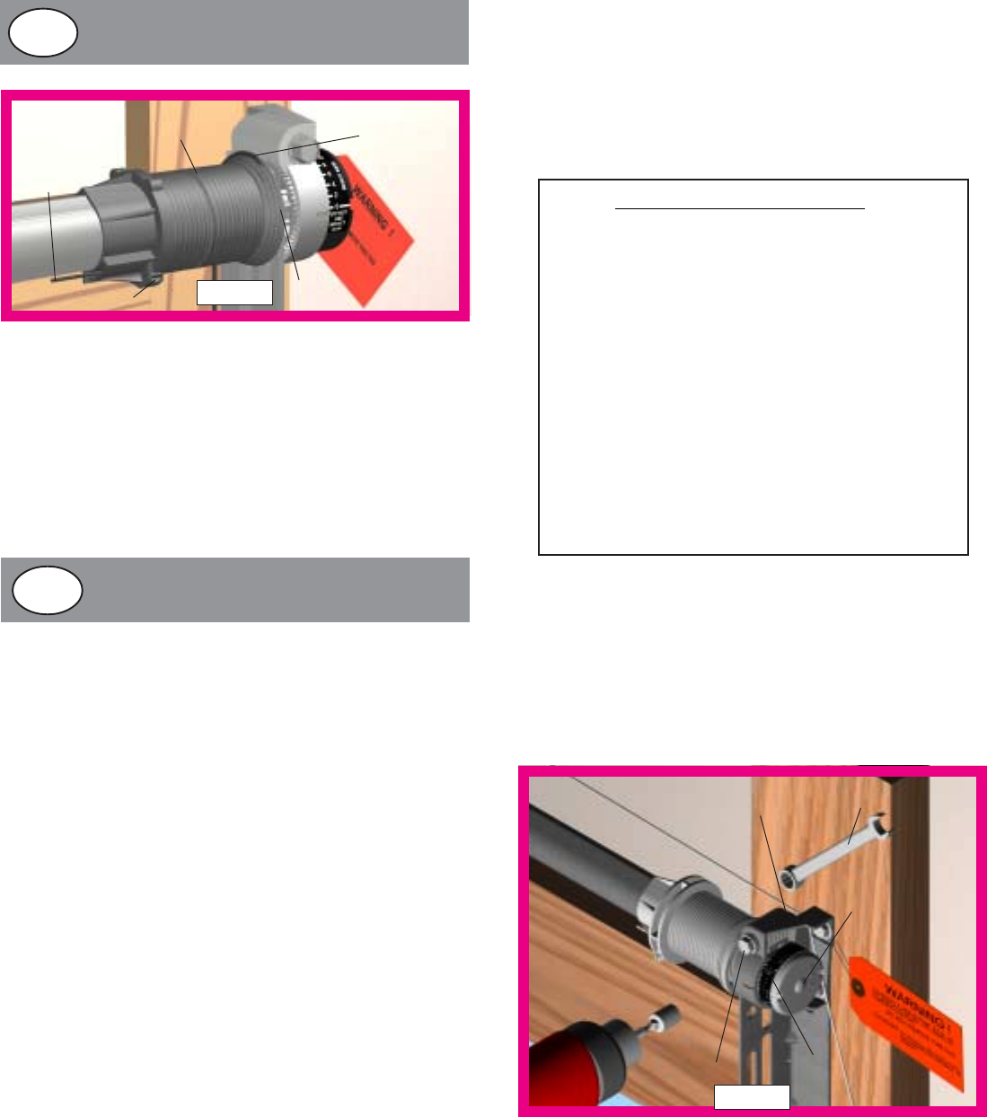
Wind Counterbalance Springs
7
IMPORTANT! Adjustments to the recommended number
of turns may be required. AFTER REAR SUPPORT
ASSEMBLY IS COMPLETE (located in main door manual
instructions), check door balance. If door raises off of floor
under spring tension alone, then reduce turns until door will
rest on floor. A “hot” door such as this can cause idrive™
operation problems.
FIRST
GROOVE
SET SCREW
PULL
CABLE
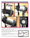
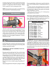
Adjust the counter balance cables by rotating the drum until
the set screw faces directly away from the header. Loosen
the set screw no more than 1/2 turn. Pull on the end of the
cable to remove all cable slack. Check to ensure the cable
is aligned and seated in the first groove of the cable drum.
Snug the set screw, then tighten an additional 1-1/2 turns.
Cut off excess cable.
DRUM
CABLE
Cable Adjustments
7/16” WRENCH
LOCK NUT
CONOE CLIP
WINDING BOLT
COUNTER
FIG. 20
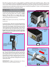
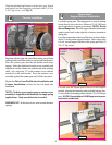
Clamp locking pliers onto both vertical tracks just above
third roller. This is to prevent garage door from rising while
winding counterbalance springs.
IMPORTANT! DO NOT USE IMPACT GUN TO
WIND SPRING(S)
Beginning with the right hand side. Press and hold in the
canoe clip. Ensure the cable is in the first groove of the
drum. Using an electric drill (high torque gear reduced to
1300 RPM preferred) with a 7/16" socket, carefully rotate
right hand winding bolt clockwise, until counter shows 2-3
turns. This will keep the counterbalance cable taut while
adjusting the left hand side counterbalance cable.
Repeat for left side on double spring TorqueMaster™
systems.
Single spring applications will require no spring pre-winding.
Ensure counterbalance cable tension is equal for both sides
prior to fully winding spring(s) to appropriate number of
turns.
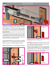
Carefully rotate the winding bolt head clockwise until the
counter show the correct number of turns for your door.
See the chart below. Repeat for the opposite side on double
spring TorqueMster™ systems.
If door raises off of floor remove 1/2 - 1 full turn from
each spring before proceeding.
After spring is wound, hold the lock nut stationary with a
7/16” wrench while rotating the winding bolt clockwise until
snug. Tightening of the lock nut prevents spring from
unwinding. Repeat for opposite side if necessary.
6’0” Door Height = 14-1/2 turns (Double
Spring) and 15 turns (Single Spring)
6’-3” Door Height = 15 turns
6’-5” Door Height = 15-1/2 turns
6’-6” Door Height = 15-1/2 turns
6’-8” Door Height = 16 turns
6’-9” Door Height = 16 turns
7’-0” Door Height = 16-1/2 turns
7’-3” Door Height = 17 turns
7’-6” Door Height = 17-1/2 turns
7’-9” Door Height = 18 turns
8’-0” Door Height = 18-1/2 turns
Door Height = Spring Turns
FIG. 19
16b
17a