


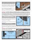
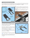
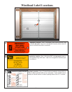

Measure the distance from the top of the windload post
to the center of the bottom strap (see Fig. 14). Use that
measurement for the displacement between the center
of the extra header lock bracket and half-hinge tube.
Position the half-hinge on the bottom mounting block
and secure the half-hinge using (2) 5/16” x 1-5/8” lag
screws. Repeat this step for remaining windload posts
if necessary. (see Fig. 13)
Slide the windload post(s) into storage header bracket(s)
and secure the bottom strap(s) to the half hinge(s) using
the wing nut and carriage bolt. Place all remaining wing
nuts and carriage bolts into the remaining straps for
storage. Insert plastic plug into hole in floor.
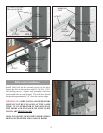
Securing Post for Storage
Locate a convenient place to store the windload post(s).
Measure and cut (2) 2 x 6” wood mounting blocks a
minimum of 10” long for each windload post. Locate
the mounting blocks horizontally on the wall as shown
in Fig. 13. Secure them adequately to the wall at the top
and bottom of the post storage location, with masonry
anchors (concrete or const.), or 12-16 penny nails (wood
const.). Measure a minimum of 6” above door as
illustrated, and mount the extra header lock bracket(s)
to the top mounting block(s) using (2) 5/16” x 1-5/8”
lag screws as shown in Fig. 13.
7
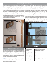
Rebalance The Door
Now that the windload post is NOT installed onto the door,
check the door’s balance, by manually opening and
closing the door. The door may be heavy because of the
extra hardware added. To accommodate the extra weight,
tension must be added to the counterbalance springs.
See chart for adding spring tension.
NOTE: Refer to the garage door’s main installation
instructions and owner’s manual for instructions on
adding/removing spring tension.
6” MIN.
(2) 5/16” X 1-1/2”
LAG SCREWS
(2) 5/16” X 1-1/2”
LAG SCREWS
HEADER LOCK
BRACKET
HALF-HINGE
TUBE
DISTANCE BETWEEN TOP
OF WINDLOAD POST AND
CENTER OF BOTTOM
STRAP
MEASURE THE
DISTANCE FROM THE
TOP OF THE WINDLOAD
POST TO THE CENTER
OF THE BOTTOM STRAP
TOP OF WINDLOAD POST
BOTTOM OF WINDLOAD POST
BOTTOM
STRAP
FIG. 13
FIG. 14
ecnalabretnuoC
metsyS
otdeddAsnruTforebmuN
metsySecnalabretnuoC
™retsaMeuqroTnrut2/1
gnirpSnoisroTnrut2/1
gnirpSnoisnetxEtnemecalpkooh"S"etacoleR