


Please Do Not Return This Product To The Store. Contact your local Wayne-Dalton dealer. To find your local Wayne-Dalton dealer,
refer to your local yellow pages business listings or go to the Find a Dealer section online at www.Wayne-Dalton.com
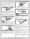
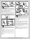
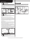
tension until door rests on the floor. If the door is hard to raise or drifts down on its own, add
spring tension. A poorly balanced door can cause garage door operator operation problems.
To adjust spring tension, fully close door. Apply vice grips to track above third track roller.
Insert a winding rod into the winding cone. On single spring doors, counterbalance lift
cable tension must be maintained by placing vice grips on torsion shaft before loosening
set screws in the winding cone. Push upward on the winding rod while carefully loosening
the set screws in the winding cone. BE PREPARED TO SUPPORT THE FULL FORCE OF THE
TORSION SPRING ONCE THE SET SCREWS ARE LOOSE. Carefully adjust spring tension 1/4
turn. Retighten both set screws in the winding cone and repeat for the other side. Recheck
door balance DO NOT ADJUST MORE THAN 1/2 TURN FROM THE RECOMMENDED NUMBER
OF TURNS.
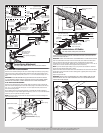
If door still does not balance correctly, contact a qualified door agency. If the door still does
not operate easily, lower the door into the closed position, UNWIND THE SPRING(S) FULLY
(Reference the insert “Removing The Old Door/Preparing The Opening” section on torsion
spring removal), and recheck the following the items:
1.) Check the door for level.
2.) Check the torsion shaft for level.
3.) Check the track spacing.
4.) Check the counterbalance lift cables for equal tension.
5.) Check the track for potential obstruction of the track rollers.
6.) Clamp locking pliers onto track and rewind springs.
IMPORTANT: IF DOOR STILL DOES NOT OPERATE PROPERLY, THEN CONTACT A TRAINED
DOOR SYSTEM TECHNICIAN.
NOTE: Now proceed with Step Lift Handles.
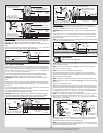
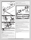
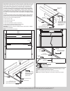
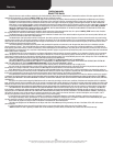
Vice clamp
Horizontal tracks
2nd Track roller
Vice clamp
5/16”-18 x 1-1/4”
Hex bolt must extend into the
track to serve as a roller stop
Perforated angle
Sound framing
members
Horizontal
track
(3) 5/16” Bolts and nuts
Perforated angle bolted
using (2) 5/16” x 1-5/8”
hex head lag screws to
ceiling member and
parallel to door
Perforated angle
Sound framing
members
Horizontal
track
(3) 5/16”
Bolts and nuts
Perforated angle bolted
using (2) 5/16” x 1-5/8”
hex head lag screws to
ceiling member and
parallel to door
5/16”-18 x 1-1/4”
Hex bolt must extend into the
track to serve as a roller stop
Horizontal tracks
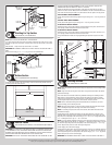
Door edges
3/4” To 7/8”
3/4” To 7/8”
Rear center
back hang
Horizontal
track
(1) 3/8” Truss head bolt
(may not be supplied)
Center of the horizontal track
Drill 3/8”
diameter hole
Horizontal
track
(1) 3/8” Nut
(may not be supplied)
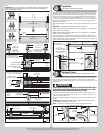
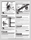
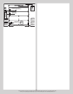
Label Placement
Tools: Step Ladder
23
IMPORTANT: USING THE ILLUSTRATION, ATTACH THE APPROPRIATE LABELS TO THE AP-
PROPRIATE LOCATION ON THE SECTION, AS SHOWN.
NOTE: The Spring Warning tag(s) are factory attached (one per spring).
NOTE: Because of different configurations, some labels may require minor relocations.
15