


Please Do Not Return This Product To The Store. Contact your local Wayne-Dalton dealer. To find your local Wayne-Dalton dealer,
refer to your local yellow pages business listings or go to the Find a Dealer section online at www.Wayne-Dalton.com
DEEP.
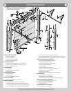
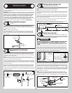
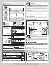
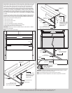
IMPORTANT: PUSH & HOLD THE HINGE LEAFS SECURELY AGAINST THE SECTIONS WHILE
SECURING WITH APPROPRIATE FASTENERS. THERE SHOULD BE NO GAP BETWEEN THE
HINGE LEAFS AND THE SECTIONS.
Center
hinge(s)
Left single
graduated end
hinge with
typical short
stem track roller
Right single
graduated end hinge
with typical short
stem track roller
(2) 1/4”-20 x 2-1/4” Carriage bolts and (2) 1/4”-20 Flange hex nuts
Intermediate I section
Bottom section
Vertical
tracks
Left double graduated
end hinge with typical
long stem track roller
Typical graduated end
hinge with typical long
stem tandem track roller
Right double graduated
end hinge with typical
long stem track roller
(2) 1/4”-14 x 1” Lag screws
2” Long
strut
Typical
section
shown.
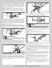
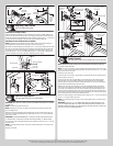
(4) 1/4”-14 x 1”
Lag screws
(2) 1/4”-20 x 2 1/4”
Carriage bolts and (2)
1/4”-20 Flange hex nuts or
(2) 1/4”-20 x 1-3/8” bolts
Single graduated end
hinge upper hinge leaf
Double graduated end hinge
upper hinge leaf
(2) 1/4”-20 x 2 1/4” Carriage bolts
and (2) 1/4”-20 Flange hex nuts or
(2) 1/4”-20 x 1-3/8” bolts
3” Long strut
(1) Strut clip
Typical sections shown.
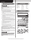
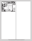
Upper hinge leaf(s)
Single or double
graduated end hinge(s)
Short edge
Long edge
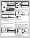
(2) 1/4”-14 x 1”
Lag screws
(3) 1/4”-14 x 1”
Lag screws
2” Long strut
Typical
section
shown.
Center hinge
upper hinge leaf
(2) 1/4”-14 x 1”
Lag screws
(2) 1/4”-14 x 1”
Lag screws
3” Long strut
Typical sections shown.
Center
hinge
Half
center
hinge
Upper hinge leaf
Upper hinge leaf
(1) Strut
clip
Short
edge
Long
edge
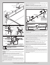
Top Section
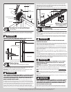
Tools: Hammer, Step ladder, Tape measure
12
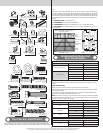
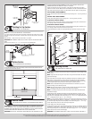
Place the top section in the opening. Temporarily secure the top section by driving a nail into
the header near the center of the door and bending it over the top section. Now, flip up the
graduated end hinge and center hinge leaves, hold tight against section, and fasten center
hinges first and end hinges last (refer to step, Stacking Sections). Vertical track alignment
is critical. For 2” track, position flag angle/wall angle between 1-11/16” (43 mm) to 1-3/4”
(44 mm) from the edge of the door; tighten the bottom lag screw. For 3” track, position flag
angle/wall angle between 2-3/16” (56 mm) to 2-1/4” (57 mm) from the edge of the door;
tighten the bottom lag screw.
Flag angles/wall angles must be parallel to the door sections. Repeat same process for other
side.
IMPORTANT: THE DIMENSION BETWEEN THE FLAG ANGLES MUST BE:
FOR 2” TRACK APPLICATIONS: DOOR WIDTH PLUS 3-3/8” (86MM) TO 3-1/2” (89 MM) FOR
SMOOTH, SAFE DOOR OPERATION.
FOR 3” TRACK APPLICATIONS: DOOR WIDTH PLUS 4-7/8” (124MM) TO 5” (127 MM) FOR
SMOOTH, SAFE DOOR OPERATION.
Complete the vertical track installation by securing the jamb bracket(s) or slots in the wall
angle and tightening the other lag screws. Push the vertical track against the track rollers so
that the track rollers are touching the deepest part of the curved side of the track; tighten all
the track bolts and nuts. Repeat for other side.
Top section
Top
section
Nail
Flag angle or
wallangle assembly
Top of flag angle or
Top of wallangle assembly
Vertical track
against rollers
Door width (2” Track)
+ 3-3/8” to 3-1/2”
Door width (3” Track)
+ 4-7/8” to 5”
2” Track Applications:
1-11/16” to 1-3/4”
3” Track Applications:
2-3/16” to 2-1/4”
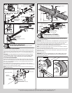
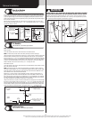
Horizontal Tracks
Tools: Ratchet wrench, 7/16” Socket, 9/16” Socket, 9/16” Wrench,
13
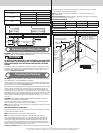
To install horizontal track, place the curved end over the top track roller of the top section.
Align the bottom of the horizontal track with the top of the vertical track. Tighten the hori-
zontal track to the flag angle/wall angle with (2) 1/4”-20 x 9/16” track bolts and (2) 1/4”-20
flange hex nuts.
WARNING WARNING
DO NOT RAISE DOOR UNTIL HORIZONTAL TRACKS ARE SECURED AT REAR,
AS OUTLINED IN STEP, REAR BACK HANGS, OR DOOR COULD FALL FROM
OVERHEAD POSITION CAUSING SEVERE OR FATAL INJURY.
Level the horizontal track assembly and bolt the horizontal track angle to the first encoun-
tered slot in the flag angle/wall angle using (1) 3/8”-16 x 3/4” truss head bolt and (1) 3/8”-
16 hex nut. Repeat for other side.
Remove the nail that was temporarily holding the top section in place, installed in step, Top
Section.
IMPORTANT: FAILURE TO REMOVE NAIL BEFORE ATTEMPTING TO RAISE DOOR COULD
CAUSE PERMANENT DAMAGE TO TOP SECTION.
NOTE: If an opener will be installed, position horizontal tracks slightly above level.
Flag angle
1/4”-20 x 9/16”
Track bolts
1/4”-20
Flange hex nuts
Horizontal
track
3/8”-16 Hex nut
Horizontal
track angle
3/8”-16 x 3/4”
Truss head bolt
Horizontal
track
Vertival track Or Wall angle
10