


Please Do Not Return This Product To The Store. Call Us Directly! Our Trained Technicians Will Answer Your Questions and/or Ship Any Parts You May Need
You can reach us Toll Free at 1-888-827-3667 for Consumer Assistance or online at www.wayne-dalton.com
23
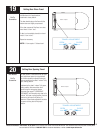
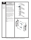
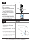
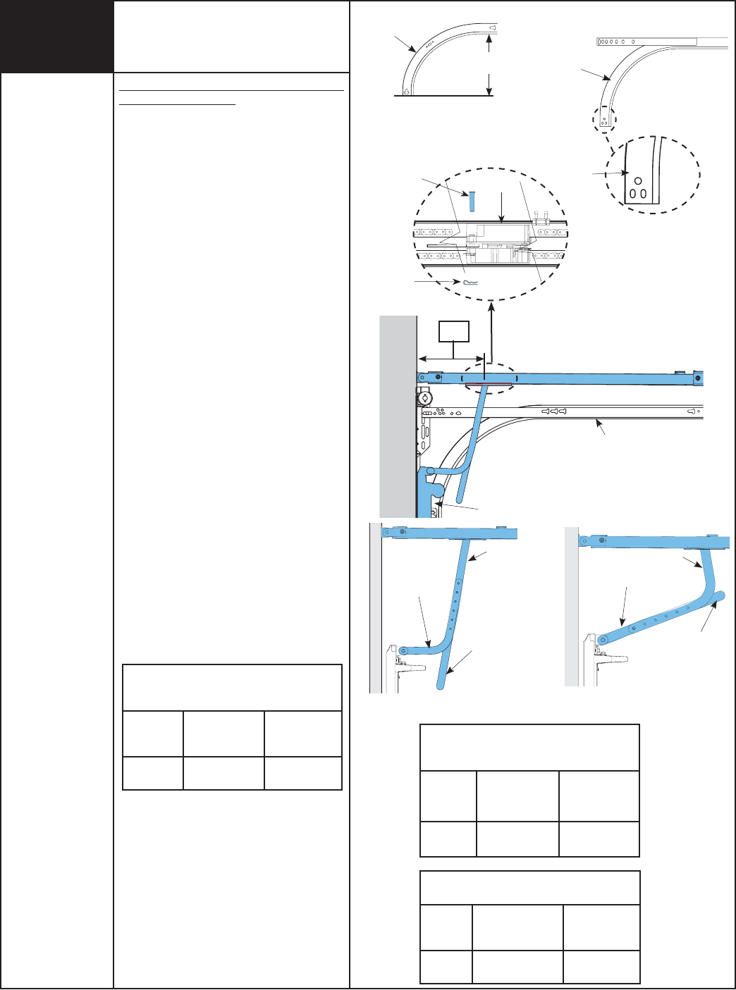
DETERMINE THE WAYNE-DALTON TRACK
RADIUS BEING USED:
FOR MOUNT HOPE AND PENSACOLA
TRACK:
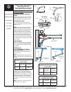
Measure the curved ends of the horizontal
track
to determine if you have a 12” or 15”
radius horizontal track, as shown in FIG. 1.
FOR PORTLAND TRACK:
The horizontal tracks are stamped with
radius on the side of the horizontal track, as
shown in FIG. 1.1.
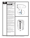
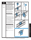
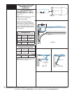
NOTE: If necessary, remove the upper arm
(straight arm) from the trolley, to use the
lower arm (curved arm). Remove the hairpin
cotter from the clevis pin at the front of
trolley and slide clevis pin out far enough
to slide the upper arm out between the left
and right side of trolley body. Position the
lower door arm so the end with the single
hole lines up with the clevis pin. Slide clevis
pin completely back into trolley and reinstall
hairpin cotter.
LOW HEADROOM:
If you have low headroom track, as shown
in FIG. 1.6 on page 24, then proceed with
“Low Headroom Trolley Positioning Charts”
on page 24.
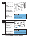
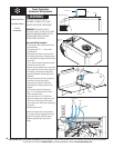
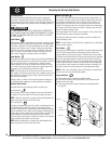
STANDARD LIFT:
Using the STANDARD LIFT TROLLEY
POSITIONING CHARTS, refer to DIM “X” to
set the distance from header to trolley, as
shown in FIG. 1.2.
NOTE: Depending on your setup, you may
have to cut straight arm to accomplish trolley
settings.
If adjustment of the trolley position is
required, use the close travel adjustment
screw located on the bottom of the opener,
as shown in FIG 1.5 on page 24. A 1/4 turn
equals approximately 1” of trolley travel; turn
clockwise to decrease distance (forward)
and counter-clockwise to increase distance
(forward).
NOTE: Proceed with “Connecting Door Arm
To Door” Step 18, on page 14.
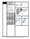
STANDARD LIFT TROLLEY POSITIONING CHART
FOR (MODEL 9700) 15” RADIUS
DIM “X”
TYPE OF ARM
BEING USED
REFERENCE
ILLUSTRATIONS
10 9/16”-
14 5/8”
STRAIGHT /
CURVED
FIG. 1.3
I
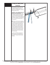
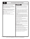
Setting Trolley Close Position/
Connecting Door Arm
(Models 9100, 9400, 9600, 5120, 5140 & 9700)
With TorqueMaster® Or Extension Springs
FIG. 1.3
Cut Straight Arm To
Accomplish Trolley
Setting
Curved
Arm
Straight Arm
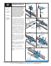
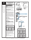
FIG. 1.4
Straight Arm
Curved Arm
Cut Straight Arm To
Accomplish Trolley
Setting
12”
Stamped
Radius
12”
FIG. 1.1
Horizontal
Track
FIG. 1
Horizontal
Track
12” OR 15”
STANDARD LIFT TROLLEY POSITIONING CHART
FOR (MODELS 9100, 9400, 9600, 5120 & 5140)
10” AND 12” RADIUS
DIM “X”
TYPE OF ARM
BEING USED
REFERENCE
ILLUSTRATIONS
11 1/2”
CURVED /
STRAIGHT
FIG. 1.4
STANDARD LIFT TROLLEY POSITIONING CHART
FOR (MODELS 9100, 9400, 9600, 5120 & 5140)
14” AND 15” RADIUS
DIM “X”
TYPE OF ARM
BEING USED
REFERENCE
ILLUSTRATIONS
13”-15”
CURVED /
STRAIGHT
FIG. 1.4
FIG. 1.2
Top Section
10”, 12”, 14”, OR 15”
Standard Lift Track
“X”
Clevis Pin
Hairpin Cotter
Trolley
TOP VIEW
Tools Needed:
Needle Nose Pliers
Adjustable Wrench
Ratchet Wrench
7/16” Socket
9/16” Socket
Hacksaw