


Please Do Not Return This Product To The Store. Call Us Directly! Our Trained Technicians Will Answer Your Questions and/or Ship Any Parts You May Need
You can reach us Toll Free at 1-888-827-3667 for Consumer Assistance or online at www.wayne-dalton.com
14
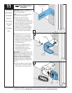
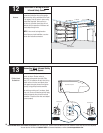
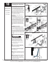
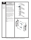
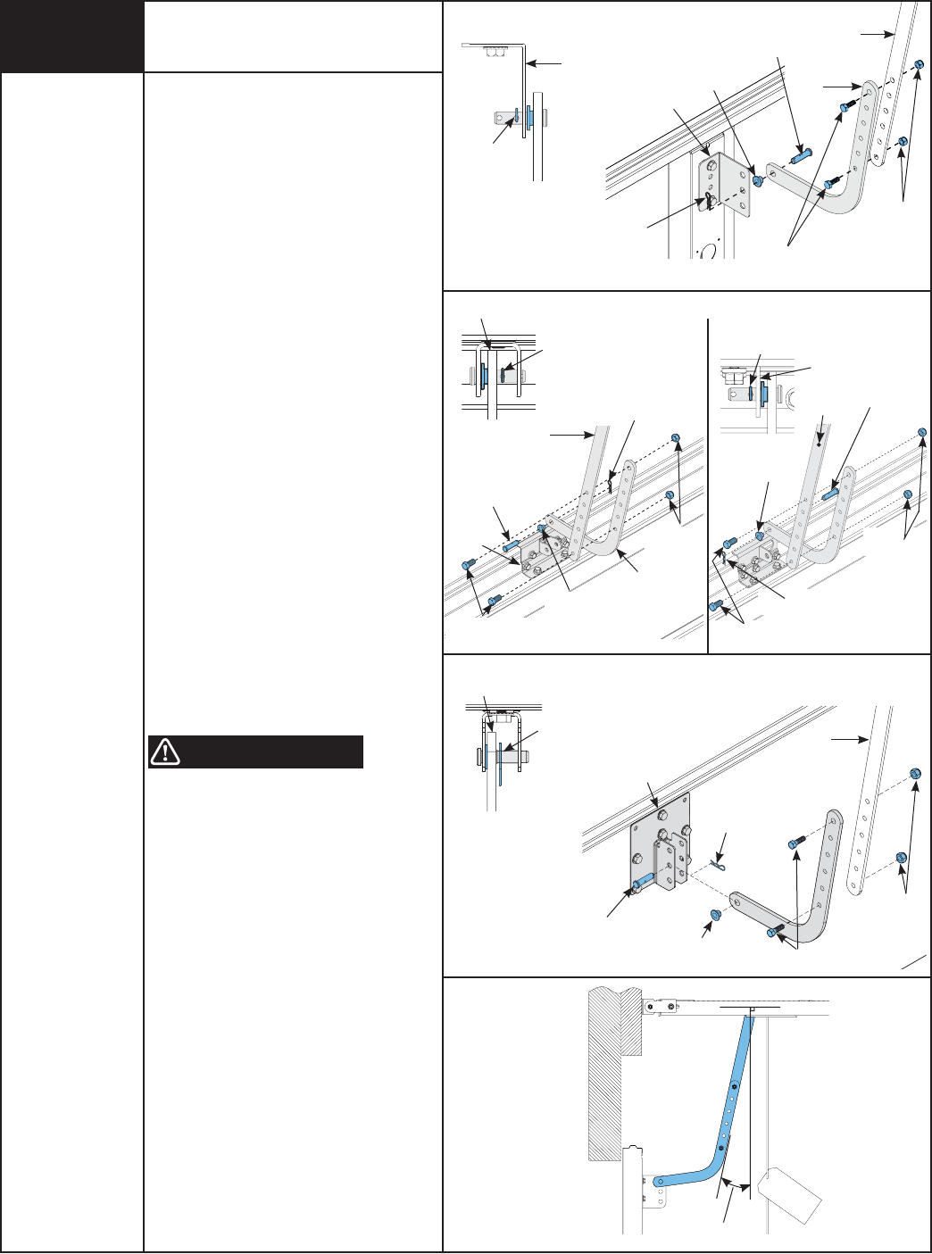
Typical Installation:
Place nylon shoulder bushing in lower arm
hole in curved end (single hole). Place door
arm on right side of door bracket. Insert
5/16” x 1-1/4” multi-grip clevis pin through
nylon shoulder bushing, lower door arm and
middle hole of door bracket. Install hairpin
cotter through hole (Closest to door bracket)
of multi grip clevis, as shown.
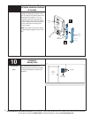
For Models: 9100, 9400, 9600, 5120,
5140 And 9700
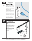
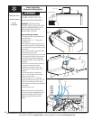
Place nylon shoulder bushing in lower arm
hole in curved end (single hole). Place the
lower door arm between the tabs (or the right
side of single tab) and insert 5/16” x 1-1/4”
multi-grip clevis pin through nylon shoulder
bushing, lower door arm and hole(s) of door
bracket. Install hairpin cotter through hole
(Closest to door arm “Double Tab” or door
bracket “Single Tab”) of multi grip clevis, as
shown.
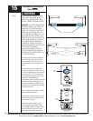
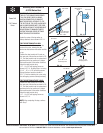
For Models: 9700 And 9800
Place nylon shoulder bushing in lower arm
hole in curved end (single hole). Place the
lower door arm between the tabs and insert
5/16” x 1-1/4” multi-grip clevis pin through
nylon shoulder bushing, lower arm and holes
of door bracket. Install hairpin cotter through
hole (Closest to door arm) of multi grip clevis,
as shown.
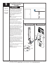
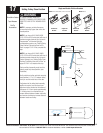
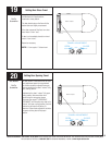
CONNECTING UPPER AND LOWER DOOR
ARMS
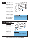
FAILURE TO USE LOCKING NUT CAN
RESULT IN ARM RELEASING AND
POSSIBLE RESULTING IN PROPERTY
DAMAGE AND/OR PERSONAL INJURY.
Align upper and lower door arm pieces to
nearest matching holes.
NOTE: It may be necessary to apply down-
ward pressure on the door or slightly raise
the door during this process.
Secure upper and lower door arms to each
other using two 1/4”-20 x 3/4” hex head
bolts and nylock nuts.
NOTE: Install the hex head bolts as far apart
as possible, when positioning the upper and
lower arms.
NOTE: Door arm angle must be 10° to 30°
degrees (see illustration). If not, repeat “Set-
ting Trolley Close Position” and increase or
decrease distance between trolley clevis pin
and inside face of the door.
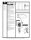
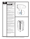
18
Connecting Door Arm to Door
Tools Needed:
Adjustable Wrench
Ratchet Wrench
7/16” Socket
9/16” Socket
WARNING
Typical Installation
10° To 30°
5/16” x 1-1/4”
Multi-grip Clevis pin
1/4”-20 x 3/4”
Hex Head Bolt
Nylon Shoulder
Bushing
Hairpin Cotter
Lower Arm
Upper Arm
1/4”
Nylock Nuts
Door Bracket
TOP VIEW
Hairpin Cotter
(Hole Closest to
Door Bracket)
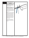
Models: 9700 And 9800
Single TabDouble Tab
TOP VIEW
TOP VIEW
Models: 9100, 9400,9600, 5120, 5140 or 9700
TOP VIEW
Hairpin Cotter
Door
Bracket
Nylon Shoulder
Bushing
5/16” x 1-1/4”
Multi-grip Clevis pin
Lower Arm
Upper Arm
1/4”
Nylock Nuts
1/4”-20 x 3/4”
Hex Head Bolt
Hairpin Cotter
(Hole Closest to
Door Arm)
Lower Arm
Door Bracket
Hairpin Cotter
(Hole Closest to
Door Bracket)
Door Bracket
Lower Arm
Hairpin Cotter
(Hole Closest to
Door Arm)
Door
Bracket
5/16” x 1-1/4”
Multi-grip Clevis pin
1/4”-20 x 3/4”
Hex Head Bolt
Nylon Shoulder
Bushing
Lower Arm
1/4”
Nylock Nuts
Hairpin Cotter
Upper Arm
1/4”
Nylock Nuts
Hairpin
Cotter
Upper Arm
5/16” x 1-1/4”
Multi-grip Clevis pin
Door
Bracket
Nylon Shoulder
Bushing
1/4”-20 x 3/4”
Hex Head Bolt
Lower Arm