


be done to ensure proper draining
and priming.
3. Place rotating shaft seal member in
position on impeller and press into
place. Take care not to press against
polished seal surface.
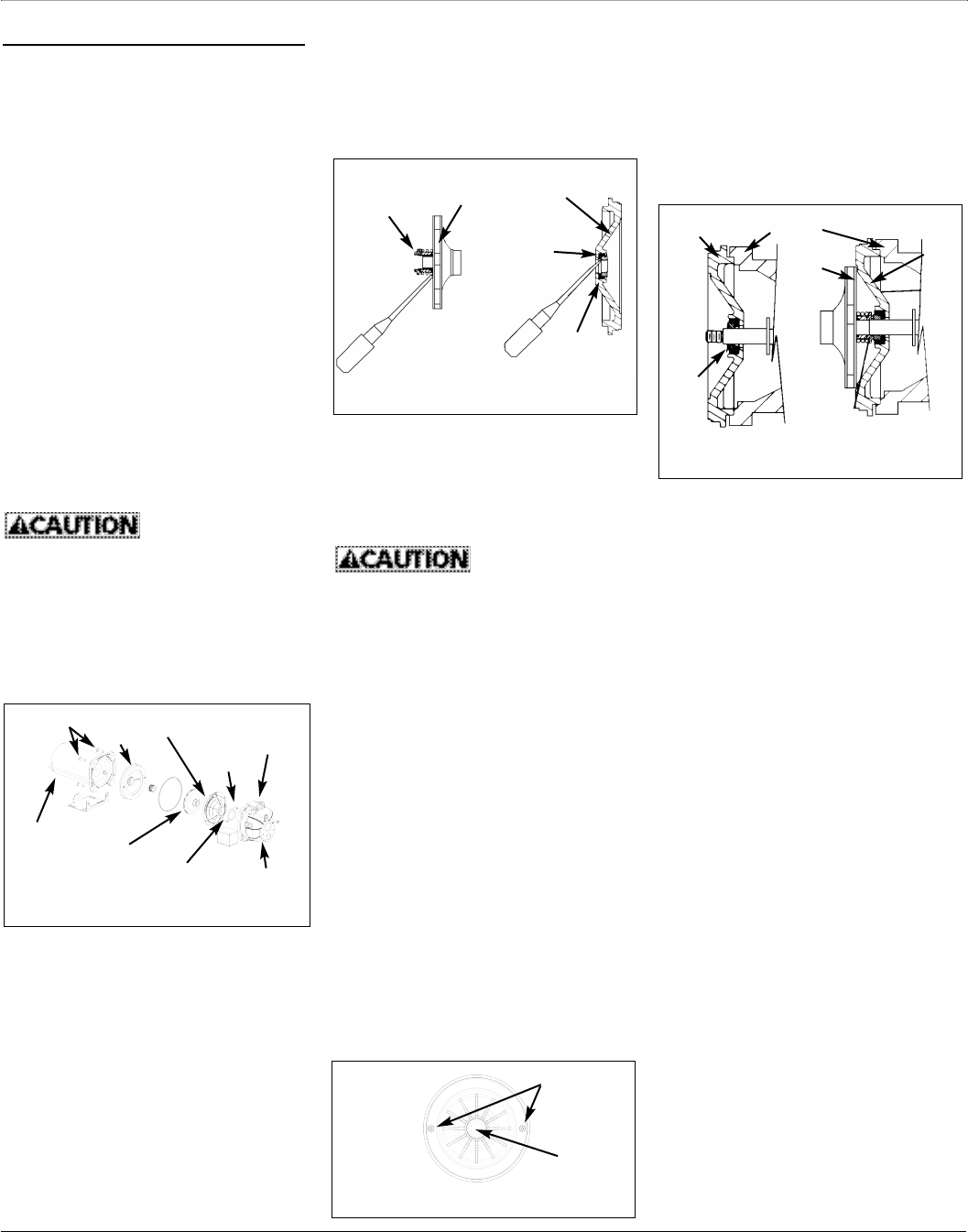
4. Position impeller on shaft and tighten
securely (Figure 15).
5. Secure diffuser to seal plate using the
two cap screws. Be sure the screws
are orientated on a horizontal line as
described in Step 2.
6. Carefully position pump housing
(volute) gasket over the diffuser onto
the seal plate. In all convertible appli-
cations the seal ring must also be
positioned on the diffuser. In all shal-
low well applications care must be
taken that the o-ring is clean and
properly positioned on the venturi.
Cleaning and positioning makes a
good seal inside the diffuser when
assembled.
7. Assemble the pump housing (volute)
to the motor using the four cap
screws. Be sure the pump housing
(volute) gasket is positioned correctly
and tighten the screws securely.
NOTE: Shaft must rotate freely and
motor end cap should be secured
before operation.
Maintenance (Cont’d)
NOTE: Once a bladder is leaking or bro-
ken, the bladder cannot be repaired. The
tank must be replaced.
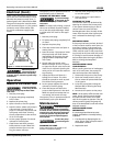
LUBRICATION
The bearing used in the pumps are life-
time lubricated at the factory and require
no additional lubrication.
PRECHARGED TANK
Some air is lost through the bladder in
any tank. To prevent tank failure, check
the tank precharge on a yearly basis.
1. Open a faucet nearest the tank and
allow all water to drain from the
tank.
2. Measure the tank precharge at the
valve stem using a tire gauge.
3. If necessary, adjust the precharge
with an air pump 28 - 30 psi on 1/2,
3/4 and 1 HP pumps.
REMOVING OLD SHAFT SEAL
Turn disconnect
switch to “off” posi-
tion.
1. Open a faucet nearest the tank and
allow all water to drain from the
tank.
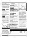
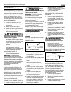
2. Remove the four cap screws holding
the pump housing (volute) to the
motor (Figure 12).
3. Separate the pump housing (volute)
from the motor to expose the dif-
fuser and the seal plate.
4. Remove the two cap screws and dif-
fuser from the seal plate to expose
the impeller.
5. Remove the small end cap on the
end of the motor opposite the
impeller.
6. With a large screwdriver or
adjustable wrench, keep the shaft
from rotating and remove the
impeller with hand (standard right
7
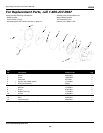
JCU50
Operating Instructions and Parts Manual
Seal
Plate
Seal
Seat
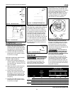
Figure 15 - Motor Shaft
hand thread). Be sure to hold onto
the cast iron seal plate when remov-
ing the impeller from the shaft.
7. Remove the seal plate.
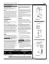
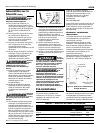
8. Pry the rotating shaft seal member
from the impeller (Figure 13).
9. Push or pry the ceramic seat free
from the seal plate (Figure 13).
10. Remove loose particles from
impeller hub and seal plate.
INSTALLING NEW SHAFT SEAL
Before handling
shaft seal parts
wipe hands clean. Dirt or grease can
damage the seal.
1. Wet the inside of the seal cavity on
seal plate and the rubber cup
enclosing the new ceramic seat with
cooking oil. Be careful not to
scratch the ceramic surface of the
seal seat and push seat enclosed in
rubber into seal cavity on seal plate.
Use a cardboard washer to protect
polished surface when pushing
against ceramic seat with any
object. Be sure to remove cardboard
washer.
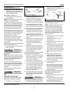
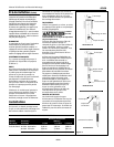
2. Carefully slip seal plate over shaft so
as not to disturb seal position in seal
plate. The seal plate must be orientat-
ed during assembly so that the two
holes are on a horizontal line across
the motor shaft and the (4) locating
pins on the back of the seal plate line
up with the tabs on the motor hous-
ing (Figure 14). This placement should
Figure 14 - Seal Plate Replacement
Screw Holes
Motor
Shaft
Motor
Impeller
Seal
Plate
Seal Facing Must
Be Clean For
Proper Seal
Figure 13 - Removing Shaft Seal &
Ceramic Seat
Seal
Plate
Ceramic
Seat
Rotating
Shaft Seal
Member
Rubber
Seat Ring
Impeller
Machine
Screws
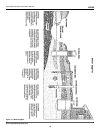
Figure 12 - Convertible Well Pump
Seal
Plate
Diffuser
Pump
Housing
(Volute)
Drain Plug
(not shown)
Cap
Screw
Cap
Screw
Impeller
Motor
www.waynewatersystems.com