


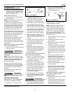
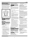

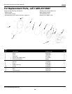
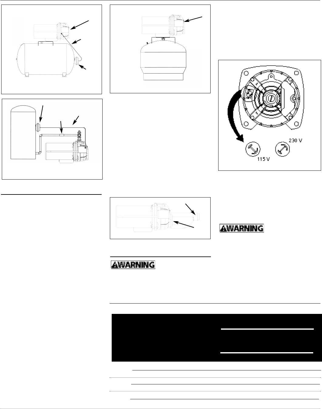
CONVERTING THE DEEP WELL PUMP TO
SHALLOW WELL OPERATION (FIGURE 9)
For shallow wells (25 feet or less), a
bolt-on shallow well jet is available as
an accessory for deep well pumps. The
jet attaches to the front of the pump
with the two bolts provided and con-
verts the deep well pump into a shal-
low well pump. The shallow well jet has
a 1” NPT inlet and a 1/8” NPT opening
for an air volume control. For optimum
performance, an incline check valve on
the inlet side of the shallow well jet is
recommended
Electrical
Risk of electrical
shock. This pump is
designed for indoor installation only.
The voltage of power supply must
match the voltage of the pump. All
above ground well pumps except
5
Operating Instructions and Parts Manual
JCU50
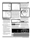
Pressure
Switch
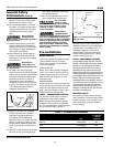
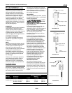
Figure 8 - Precharged Storage Tank
Pressure
Switch
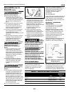
Figure 6 - Horizontal Tank
Figure 7 - Vertical Tank
Air
Volume
Control
Tubing
Air
Volume
Control
Air Volume Control
Hose
Coupling
Air
Volume
Control
Tubing
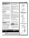
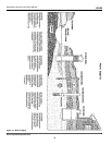
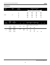
Distance In Feet
From Meter To Motor
Dual 0 51 101 201
Element To To To To
Fuse 50 100 200 300
HP Volt 250V Wire Size
115 15 14 14 12 10
230 10 14 14 14 14
115 15 14 14 10 8
230 10 14 14 14 14
115 20 12 12 10 8
230 10 14 14 14 14
CHART 3 - RECOMMENDED FUSE & WIRING DATA - 60 HZ MOTORS
1/2
3/4
1
To Air Volume
Control
Figure 9 - Shallow Well Jet
Jet
www.waynewatersystems.com
Installation (Cont’d)
3. Install a valve and isolating hose
between the system and the house
plumbing to aid in pump removal for
servicing and for reducing noise trans-
mitted through the house piping.
4. Provide a hose bib (faucet) at the
lowest point in the system to drain
for service or storage.
DEEP WELL PUMP WITH PRECHARGED
STORAGE TANK (FIGURE 8)
1. Check tank precharge using a tire
pressure gauge. The precharge pres-
sure should be 28 - 30 psi on 1/2, 3/4
and 1 HP models.
2. Check the pressure with the power
off, faucets open and no water
flowing (zero water pressure).
3. Install a valve and isolator hose
between the system and the house
plumbing to aid in pump removal
for servicing and for reducing noise
transmitted to the house through
the piping.
4. Provide a hose bib (faucet) at the
lowest point in the system to drain
for service or storage.
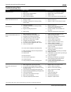
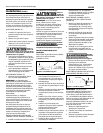
SWS50BOOST have dual voltage motors
preset at the factory to 230 volts. The
motors can be converted to 115 volts by
turning the voltage selector to the
desired voltage (See Figure 10). Use a
needle nose pliers to pull the selector
out approximately 1/4”, rotate and
then reinsert in correct position.
Select the proper size wire and fuse
(Chart 3). Time delay fuses are recom-
mended over standard fuses for motor
circuit protection. All pump motors
have built-in automatic overload pro-
tection that will prevent damage to the
motor due to overheating.
Do not connect to
electric power sup-
ply until unit is permanently grounded.
Connect ground wire to approved ground
then connect terminal provided.
A metal underground water pipe or
well casing at least 10 feet long makes
the best ground electrode. If plastic
pipe or insulated fittings are used, run
a wire directly to the metal well casing
or use a ground electrode furnished by
the power company.
Figure 10 - Voltage Selector