


5
www.waynepumps.com
Installation (Continued)
7. Slope both pipes upward toward
the pump to eliminate trapping
air. If the horizontal distance
exceeds 25 feet, see Chart 2 for the
recommended pipe sizes.
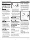
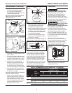
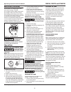
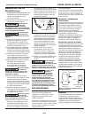
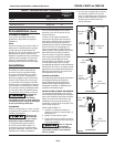
DEEP WELL PUMP WITH HORIZONTAL
AND VERTICAL STORAGE TANK
(FIGURES 6 AND 7)
1. Install the air volume control on the
tank as shown.
2. Connect the copper tube from the
air volume control to the 1/8 in. NPT
opening directly above the 1-1/4 in.
opening on the front of the pump.
3. Install a valve and isolating hose
between the system and the house
plumbing to aid in pump removal
for servicing and for reducing noise
transmitted through the house piping.
4. Provide a hose bib (faucet) at the
lowest point in the system to drain
for service or storage.
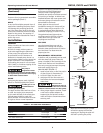
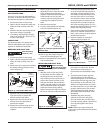
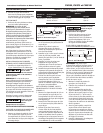
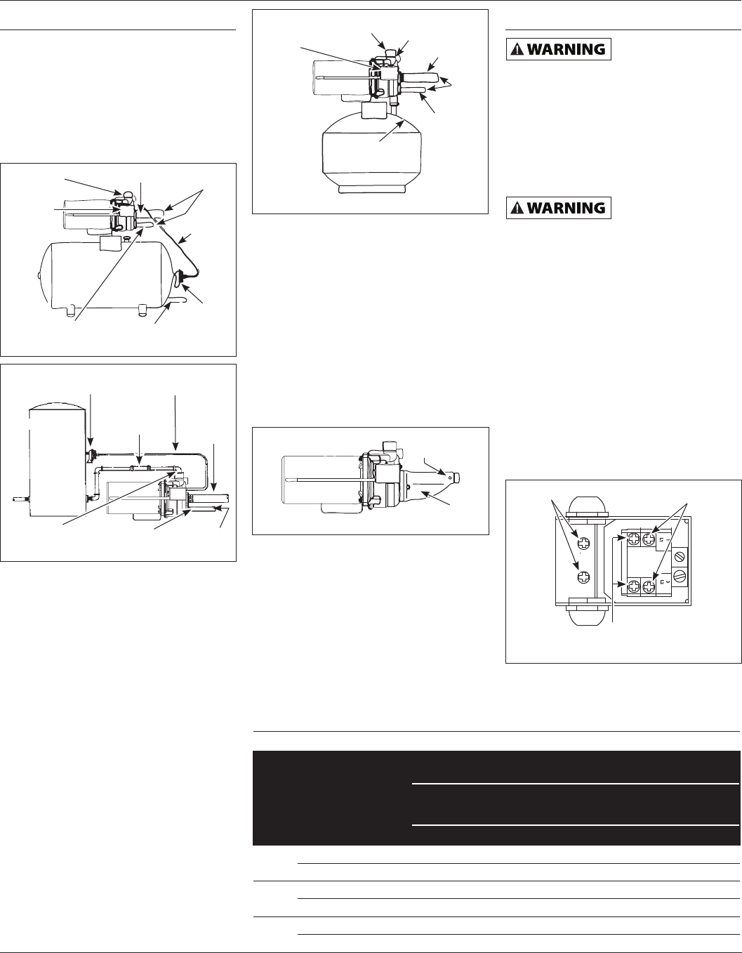
DEEP WELL PUMP WITH PRE-CHARGED
STORAGE TANK (FIGURE 8)
1. Check tank pre-charge using a tire
pressure gauge. Set air pressure in
tank to 28 psi which is 2 psi below
pressure switch cut-in level. An air
valve is located on the side and will
accept a standard fitting from a
bicycle pump or air line.
2. Check the pressure with the power
off, faucets open and no water
flowing (zero water pressure).
3. Install a valve and isolator hose between
the system and the house plumbing to
aid in pump removal for servicing and
for reducing noise transmitted to the
house through the piping.
4. Provide a hose bib (faucet) at the
lowest point in the system to drain
for service or storage.
CONVERTING THE DEEP WELL PUMP TO
SHALLOW WELL OPERATION (FIGURE 9)
For shallow wells (25 feet or less), a
bolt-on shallow well jet is available
as an accessory for deep well pumps.
The jet attaches to the front of the
pump with the two bolts provided and
converts the deep well pump into a
shallow well pump. The shallow well
jet has a 1 in. NPT inlet and a 1/8 in.
NPT opening for an air volume control.
For optimum performance, an incline
check valve on the inlet side of the
shallow well jet is recommended.
Electrical
Risk of electrical
shock. This pump is
designed for indoor installation only.
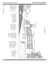
Select the proper size wire and
fuse (Chart 3). Time delay fuses are
recommended over standard fuses
for motor circuit protection. All pump
motors have built-in automatic overload
protection that will prevent damage to
the motor due to overheating.
Do not connect to
electric power supply
until unit is permanently grounded.
Connect ground wire to approved ground
then connect terminal provided.
A metal underground water pipe or
well casing at least 10 feet long makes
the best ground electrode. If plastic
pipe or insulated fittings are used, run
a wire directly to the metal well casing
or use a ground electrode furnished by
the power company.
There is only one proper ground
terminal on the unit. The terminal(s) is
located under the pressure switch cover,
is painted green and is identified as
GRD. The ground connection must be
made at this terminal (Figure 10).
The ground conductor must not be
smaller than the circuit conductors
supplying the motor.
Operating Instructions & Parts Manual
CWS50, CWS75 and CWS100
Figure 6 - Horizontal Tank
To Jet
Air
Volume
Control
Tubing
To Suction
Outlet
Air
Volume
Control
To Drive
Pressure
Switch
Prime
Plug
Figure 7 - Vertical Tank
Outlet
Air Volume
Control Tubing
Hose
Coupling
To Drive
To Jet
Prime To Suction
To
Suction
Air Volume Control
Figure 8 - Pre-charged Storage Tank
Outlet
Prime
Plug
To Drive
To Jet
28-30 psi
3/4 HP an 1 HP
To
Suction
Pressure
Switch
Figure 9 - Shallow Well Jet
To Air Volume
Control
Jet
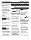
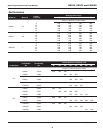
CHART 3 - RECOMMENDED FUSE AND WIRING DATA - 60 HZ MOTORS
HP Volt
Dual
Element
Fuse
250V
Distance in Feet
From Meter to Motor
0 51 101 201
to to to to
50 100 200 300
Wire Size
1/2
115 15 14 14 12 10
230 10 14 14 14 14
3/4
115 15 14 14 10 8
230 10 14 14 14 14
1
115 20 12 12 10 8
230 10 14 14 14 14
L2
3
L1
1
Figure 10 - Electrical Connections
Line
Motor
Ground
Screw