


11Waterford E61 Gas Fireplace Insert
Reduction Kit to Lower
Btu Rating for Emerald
E61 Gas Insert
Natural Gas - Kit #: 260-920
Propane - Kit # 260-922
THIS CONVERSION MUST BE
DONE BY A QUALIFIED
GAS FITTER
IF IN DOUBT DO NOT DO THIS
CONVERSION !!
Natural Gas Conversion Kit 260-920
Contains:
Qty.Part # Description
1 904-593 Burner Orifice #40 (Natural Gas)
1 908-365 Decal "Converted to 27,000 Btu"
1 908-363 Instruction Sheet
Propane Conversion Kit 260-922 Contains:
Qty.Part # Description
1 904-390 Burner Orifice #52 (Propane)
1 908-366 Decal "Converted to 29,000 Btu"
1 908-363 Instruction Sheet
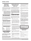
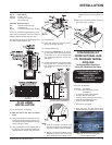
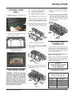
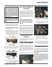
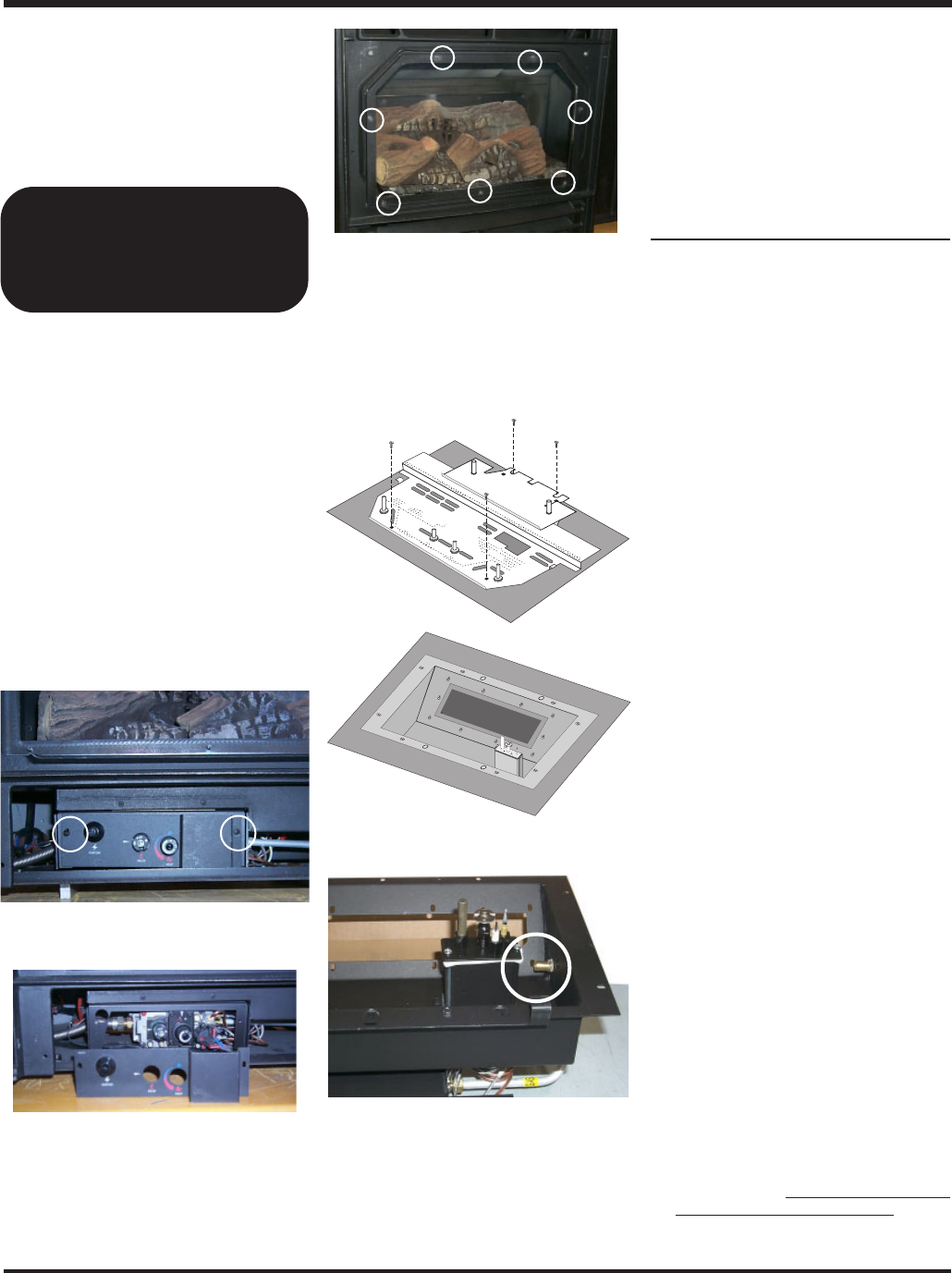
1) Shut off the gas supply.
2) Open the lower grill and remove the 2
screws holding the control panel in place.
Burner Orifice
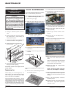
3) Remove the door by lifting it slightly up and
off the front face. Remove the 7 nuts that
secure the front glass bracket holding the
center glass in place.
Remove the 2 screws holding the
Control Panel in place.
Remove the 7 nuts holding the Front Glass
Bracket to the front face.
CAUTION: Don't let the glass drop.
INSTALLATION
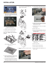
4) Carefully remove the logs and embers.
5) Remove burner.
Note: Use a magnetic type screwdriver
if possible.
6) Remove burner orifice with a 1/2" wrench
and discard.
7) Reinstall new burner orifice (NG stamped
#40 or LP stamped #52) and tighten.
8) Reverse steps 5) to 1).
9) Attach the label "This unit has been con-
verted to..." on top of the Serial # decal over
the higher Btu information.
10)Check for gas leaks.
11)Check inlet and outlet pressures.
12)Check operation of flame control. Check
for proper flame appearance and glow on
logs.
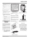
GAS PIPE PRESSURE
TESTING
The appliance must be isolated from the gas
supply piping system by closing its individual
manual shut-off valve during any pressure
testing of the gas supply piping system at test
pressures equal to or less than 1/2 psig. (3.45
kPa). Disconnect piping from valve at pres-
sures over 1/2 psig.
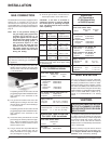
The unit is preset to give the correct gas input
at the specified manifold pressures shown on
the label. The maximum gas manifold pressure
is:
Natural Gas: 3.8" w.c.
Propane: 11" w.c.
The manifold pressure is controlled by a reg-
ulator built into the gas control, and should be
checked at the pressure test point. The pres-
sure check should be carried out with the unit
burning and the setting should be with in the
limits specified.
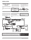
Note: To properly check gas pressure,
both inlet and manifold pressures
should be checked using the valve
pressure ports on the valve.
1) Make sure the valve is in the "OFF" position.
2) Loosen the "IN" and/or "OUT" pressure
tap(s), turning counterclockwise with a 1/
8" wide flat screwdriver.
3) Attach manometer to "IN" and/or "OUT"
pressure tap(s) using a 5/16" ID hose.
4) Light the pilot and turn the valve to "ON"
position. Read manometer.
5) The pressure check should be carried out
with the unit burning and the setting should
be within the limits specified on the safety
label.
6) When finished reading manometer, turn off
the gas valve, disconnect the hose and
tighten the screw (clockwise) with a 1/8"
flat screwdriver. Note: Screw should be
snug, but do not over tighten