


8 Waterford E61 Gas Fireplace Insert
INSTALLATION
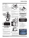
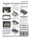
VENTING
THE APPLIANCE MUST NOT BE CON-
NECTED TO A CHIMNEY FLUE SERV-
ING A SEPARATE SOLID FUEL BURN-
ING APPLIANCE.
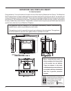
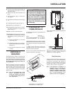
This appliance is designed to be attached to two
3" (76mm) co-linear aluminium flex running the
full length of the chimney. The flue length must
be a minimum length of 8' (2.44m) and a maxi-
mum of 35' (10.7m). See chart for minimum
distances from roof. Periodically check that the
vent is unrestricted.
Masonry chimneys may take various contours
which the flexible liner will accommodate. How-
ever, keep the flexible liner as straight as
possible, avoid unnecessary bending.
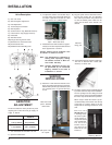
HIGH ELEVATION
This unit is approved in Canada (CAN/CGA-
2.17-M91) for altitudes to 2000 ft. (610m) using
the factory -installed burner orifice. For instal-
lations from 2000 ft (610m) to 4500 ft (1370m)
the orifice sizes (DMS) for the Natural Gas and
Propane units must be changed. See the rating
plate for details. For installations above 4500 ft.
refer to current ANSI Z223.1 Sc8-8.1.2a ap-
pendix F or CAN/CGA-B149.1, for resizing
orifice.
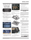
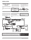
GAS CONNECTION
The Emerald Insert is factory equipped to burn
Natural Gas, if necessary the unit can be
converted to burn Propane by using Conver-
sion Kit # 260-960. For minimum and maximum
supply pressure see the System Data table on
page 8.
Note: Prior to any pressure testing of
the gas supply piping system that
exceeds test pressures of 1/2
psig, this appliance and its individ-
ual shut-off valve must be discon-
nected from the piping system. If
test pressures equal to or less
than 1/2 psig are used then this
appliance must be isolated from
the piping system by closing its
individual manual shut-off valve
during the testing.
GAS CONNECTION WARNING:
Only persons licensed to work with gas piping
may make the necessary gas connections to
this appliance.
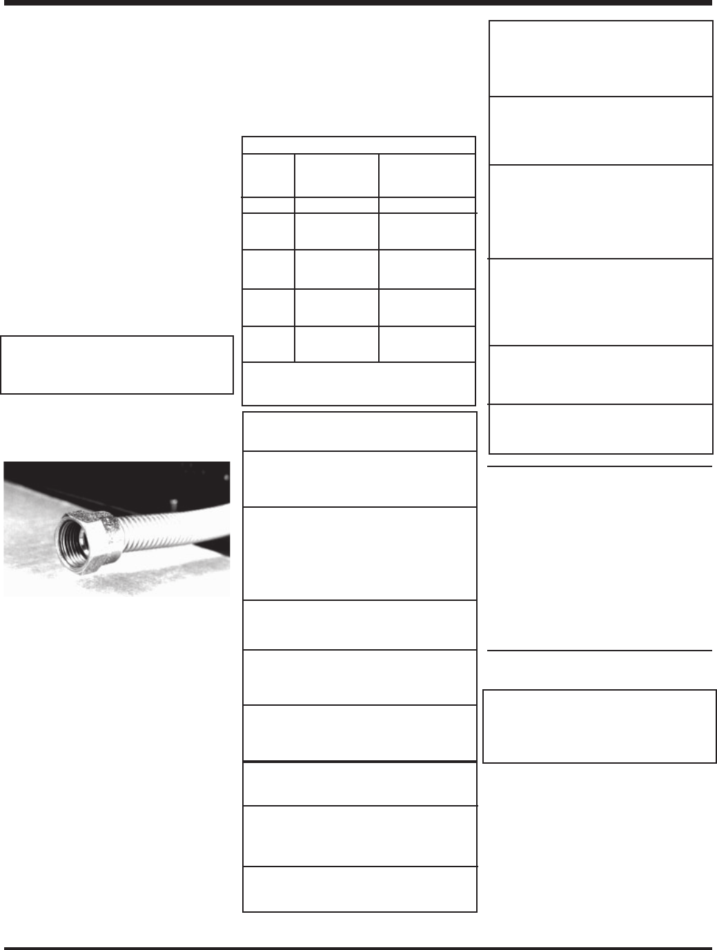
1) The gas inlet is located on the end of the
flexible pipe that emerges from the lower
left rear corner of the unit. The inlet fitting is
a 1/2" female flare.
A separate gas shut-off valve and a 1/8" IPS
plugged tapping should be installed immedi-
ately upstream of the connection to the
appliance.
2) The gas inlet is located on the end of the
flexible pipe that emerges from the lower
left rear corner of the unit. The inlet fitting is
a 1/2" female flare.
A separate gas shut-off valve and a 1/8" IPS
plugged tapping should be installed immedi-
ately upstream of the connection to the
appliance.
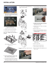
3) Locate the center point where the vent will
pass through the chimney above the appli-
ance. Move the appliance into the exact
location where it is to be installed. Ensure
that the Insert is level.
4) The gas control valve is provided with two
"IN" and "OUT" pressure taps, and are
easily accessible for a test gauge connec-
tion (see diagram on page 12).
5) Once the gas has been connected ensure
that the pilot valve is in line with burner.
CAUTION: If the door is removed or
opened for servicing, it must be replaced
and closed prior to operating the appli-
ance. The glass must be fixed in the door
when operating.
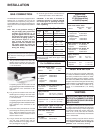
Recommended Gas Pipe Diameter
Pipe Schedule 40 Tubing,
Length Pipe Type L
(feet) Inside Diameter Outside Diameter
NG LP NG LP
0 - 10 1/2" 3/8" 1/2" 3/8"
1.3cm 1.0cm 1.3cm 1.0cm
10 - 40 1/2" 1/2" 5/8" 1/2"
1.3cm 1.3cm 1.6cm 1.3cm
40 - 100 1/2" 1/2" 3/4" 1/2"
1.3cm 1.3cm 2.0cm 1.3cm
100 - 150 3/4" 1/2" 7/8" 3/4"
2.0cm 1.3cm 2.3cm 2.0cm
Note: Never use plastic pipe. Check to confirm
whether your local codes allow copper tubing
or galvanized pipe.
System Data:
E61 Converted to
27,000 (Natural Gas)
or 29,000 (Propane)
For 0 to 4500 feet altitude
Burner Inlet Orifice Sizes:
Natural Gas Propane
Burner #40 #52
Max. Input Rating
- Natural Gas 27,000 Btu/h
- Propane 29,000 Btu/h
Min. Input Rating
- Natural Gas 13,500 Btu/h
- Propane 14,500 Btu/h
Output Capacity with blower Off
Natural Gas 21,168 Btu/h
Propane 23,258 Btu/h
Output Capacity with blower On
Natural Gas 21,708 Btu/h
Propane 23,925 Btu/h
Supply Pressure
Natural Gas min. 5.0" w.c.
Propane min. 12.0" w.c.
Manifold Pressure
Natural Gas 3.8" +/- 0.2" w.c.
Propane 11" +/- 0.2" w.c.
System Data
For 0 to 2000 feet altitude
Burner Inlet Orifice Sizes:
Natural Gas Propane
Burner #32 #50
Max. Input
- Natural Gas 38,000 Btu/h
- Propane 35,000 Btu/h
Min. Input
- Natural Gas 19,000 Btu/h
- Propane 17,500 Btu/h
Max. Output Capacity with blower On
Natural Gas 30,666 Btu/h
Propane 28,700 Btu/h
Supply Pressure:
Nat. Gas min. 5" w.c. (1.25 kPa)
Propane min. 12" w.c. (3.0 kPa)
Manifold Pressure
Natural Gas 3.8" +/- 0.2" w.c. (0.94 kPa)
Propane 11" +/- 0.2" w.c. (2.7 kPa)
System Data - HIGH ELEVATION
For 2,000 - 4,500 feet altitude
Burner Inlet Orifice Sizes:
Natural Gas
Burner #33
Max. Input .
- Natural Gas 36,100 Btu/h