


14 Waterford E61 Gas Fireplace Insert
INSTALLATION
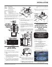
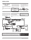
WIRING DIAGRAM
This heater does not require a 120V A.C.
supply for operation. In case of a power failure,
the burner switch and the optional remote
control/thermostat will continue to operate.
However, a 120V A.C. power supply is needed
for the fan/blower operation.
Caution: Ensure that the wires do
not touch any hot surfaces and are
away from sharp edges.
Verify proper operation after serv-
icing.
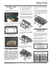
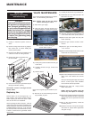
OPTIONAL REMOTE
CONTROL
Use the Waterford Remote Control Kit approved
for this unit. Use of other systems may void your
warranty.
The remote control kit comes with a hand held
transmitter, a receiver and a wall mounting
plate.
1) Choose a convenient location on the wall to
install the receiver and the receptacle box
(protection from extreme heat is very im-
portant). Run wires from the fireplace to
that location, use Thermostat Wire Table.
2) Connect the wires as per the wiring dia-
gram below.
CAUTION
Do not connect the millivolt
remote control wires to the
120V wires.
3) Install 3 AAA alkaline batteries in transmit-
ter and 4 AA alkaline batteries in the
receiver. Install the receiver and its cover
in the wall. Switch the remote receiver to
"remote" mode. The remote control is now
ready for operation.
If any of the original wires as supplied
with the appliance must be replaced, it
must be replaced with CSA type SEW
(200
o
C) or its equivalent.
CAUTION: Label all wires prior to dis-
connection when servicing controls.
Wiring errors can cause improper and
dangerous operation.
WARNING: Electrical Grounding Instructions
This appliance is equipped with a three pronged (grounding) plug for your protection
against shock hazard and should be plugged directly into a properly grounded three-
prong receptacle. Do not cut or remove the grounding prong from this plug.