


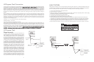

LEAK TESTING
Although all gas connections on the unit are leak tested at the factory prior to shipment, a complete gas tightness check must
be performed at the installation due to possible mishandling in shipment or excessive pressure unknowingly being applied to
the unit. Periodically check the whole system for leaks, or immediately check if the smell of gas is detected.
1. Do not smoke while leak testing. Extinguish all flames.
2. Never leak test with an open flame.
3. Make a soap solution of one part liquid detergent and one part water. You will need a spray bottle, brush or towel to apply
the solution to the fittings. For LP/Propane units, check with a full cylinder.
4. Check that all control knobs are in the “OFF” position.
5. Turn cylinder valve knob counter clockwise one turn to open.
6. Blowing bubbles in the soap solution indicates that a leak is present.
7. Stop a leak by tightening the loose joint or by replacing the faulty part with a replacement part recommended by the
manufacturer. Do not attempt to repair the cylinder valve if it should become damaged. The cylinder must be replaced.
8. If you are unable to stop a leak, shut off the gas supply at the cylinder valve. Remove the cylinder from the unit. Call an
authorized gas appliance service technician or LP/Propane gas dealer. Do not use the unit until the leak is corrected.
9. After checking for leaks, push in and turn any control knob to release the pressure in the hose and manifold. Turn off the
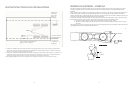
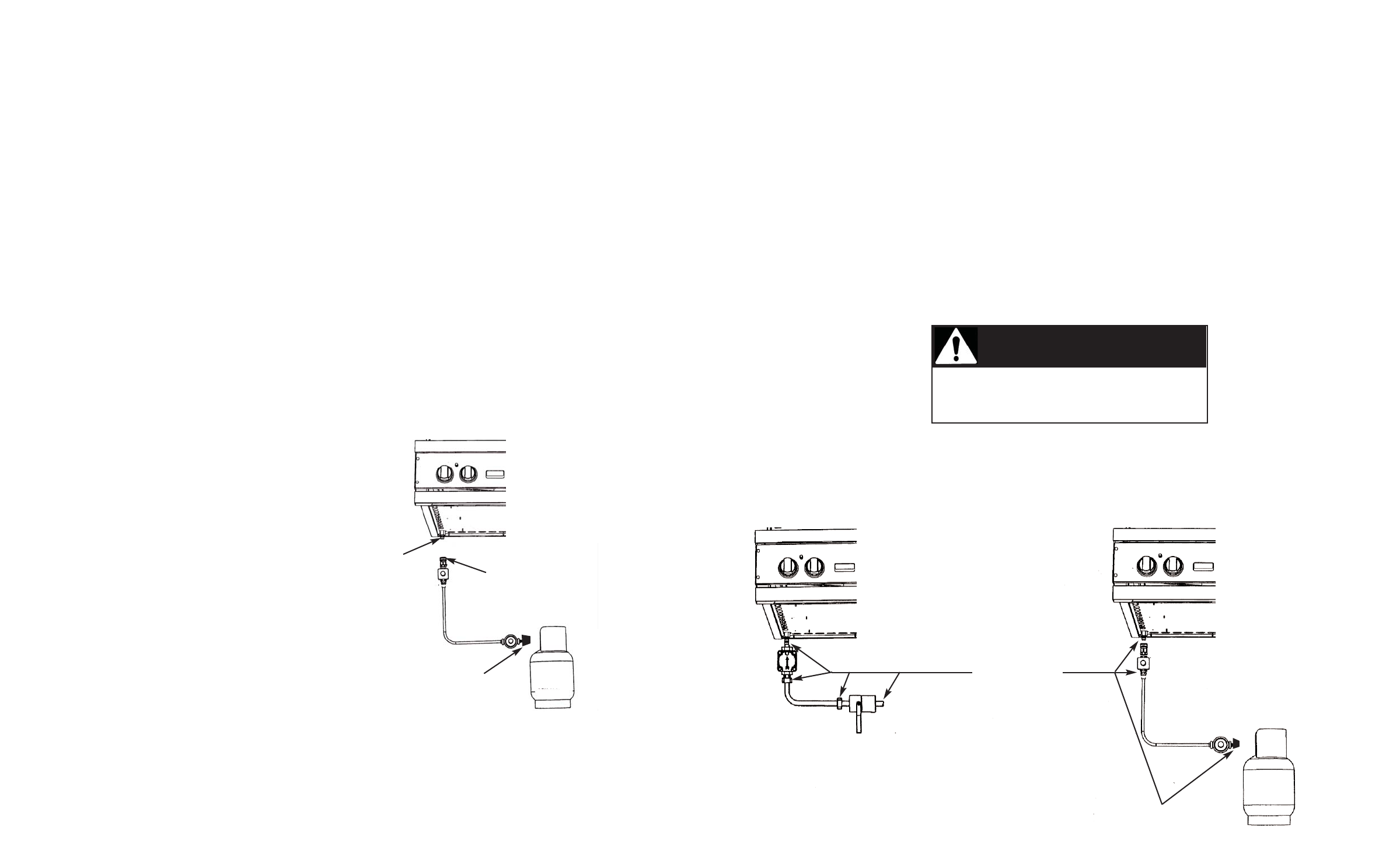
LEAK TEST
POINTS
Tank
3/8” flare
adaptor
Type 1, QCC-1
connector
Tank
3/8” flare coupling
7
6
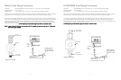
LP/Propane Tank Connection
Outdoor side burners orificed for use with LP/Propane gas come equipped with a high capacity hose/regulator assembly
for connection to a standard 20 lb. LP/Propane cylinder equipped with a Type 1, QCC-1 connector. (See LP/Propane tank
requirements on page 6). Hose assembly must comply with Elastomeric Composite Hose and Couplings for Conducting
Propane and Natural Gas, CAN/CGA-8.1 standard or the Thermoplastic Hose and Hose Couplings for Conducting
Propane and Natural Gas CAN1-8.3 standard. (See LP/Propane tank requirements below). Each tank is supplied with a
dust cap. Place dust cap on cylinder valve outlet whenever the cylinder is not in use. Only install the type of dust cap on
the cylinder valve outlet that is provided with the cylinder valve. Other types of caps or plugs may result in leakage of
propane.
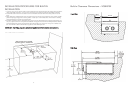
Built-in installations must be plumbed using a fixed/hard line if the unit is going to be operated at a distance exceeding
3 feet (0.91 meters) from the fuel supply per ANSI Z21.24. Also, in a built-in construction where an LP/Propane tank is
going to be used, there MUST be some type of support (braces, cut-out, etc.) to prevent tank from moving within the
installation. The support must also allow the LP/Propane tank to withstand a horizontal tipping force equal to the weight
of the tank without tipping over. The tank can not tip over or deflect more than 1.00 inch when a 38 lb. horizontal force
is applied to a 20 lb. LP/Propane tank.
Connection: 1/2” (1.3 cm) NPT male with a 3/8” (.95) flare adapter
Operating Pressure: 10.0” W.C.P.
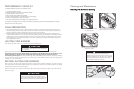
To connect to LP/Propane regulator/hose assembly:
Although the flow of gas is stopped when the quick disconnect system is disconnected as part of its safety feature, you
should always turn the LP/Propane tank main valve “OFF” after each use and during transport of the tank or unit. First
connect the regulator to the unit by screwing the 3/8” flare coupling to the 3/8” flare adapter. Connect to the tank valve
by screwing the Type 1, QCC-1 connector to the LP/Propane tank. Open the tank valve and check the connection
between the regulator and the Type 1, QCC-1 fitting for leaks with a soapy water solution. If bubbles appear, tighten the
connection. Repeat until all leaks have been stopped. ALWAYS CHECK FOR LEAKS AFTER EVERY LP/PROPANE TANK
CHANGE. Any joint sealant used must be an approved type and be resistive to the actions of LP/Propane gas.
LP/Propane Tank
Requirements
A dented or rusty LP/Propane tank may be hazardous and
should be checked by your tank supplier. Never use a cylinder
with a damaged valve. All tanks should be equipped with an
OPD (overfilling protection device). This is a DOT requirement
for all tanks purchased after October 1, 1998 and will ensure
that the tank is not overfilled. The LP/Propane tank should be
a standard 5-gal, 20 lb. gas cylinder tank approximately 12” in
diameter and 18” high which must be constructed and marked
in accordance with the Specifications for LP/Propane Gas
Cylinders of the U.S. Department of Transportation (D.O.T.) or
the National Standard of Canada, CAN/CSA-B339, Cylinders,
Spheres and Tubes for Transportation of Dangerous Goods; and
Commission. The cylinder connection device must be
compatible with the Type 1, QCC-1 connector on the outdoor
cooking appliance. All LP/Propane tanks must be mounted in a
vertical position for proper ventilation. The cylinder must be
provided with a shut-off valve terminating in an LP/Propane gas
supply cylinder valve outlet specified. The cylinder supply
system must be arranged for vapor withdrawal and provided
with a listed overfilling prevention device. If the appliance is
stored indoors the cylinder must be disconnected and removed
from the appliance. Each tank is supplied with a dust cap. Place
dust cap on cylinder valve outlet whenever the cylinder is not in
use. Only install the type of dust cap on the cylinder valve outlet
that is provided with the cylinder valve. Other types of caps or
*Tank must be
mounted in
vertical position
for proper
ventilation
Before placing into operation, always check for gas
leaks with a soapy water solution. DO NOT USE AN
OPEN FLAME TO CHECK FOR LEAKS!
CAUTION
*Tank must be
mounted in
vertical position
for proper
ventilation