


18
105706
DIRECT-VENT GAS FIREPLACE HEATER
VDVF36P and VDVF36ST Series
®
INSTALLATION
Continued
INSTALLING LOG SET
Before proceeding, make sure the gas con-
trol valve is in the “OFF” position. Logs
have been packaged separately to prevent
damage to glass or refractory.
1. Remove top and bottom louvers by si-
multaneously pulling both top end
spring latches towards the center of the
appliance until they are disengaged from
locating holes. Repeat for bottom end
spring latches and pull outward. Reverse
procedure to install louvers back.
2. Remove the screen rod by sliding
spring clip on one end toward the cen-
ter. Slide rod into screen rod hole until
other end of rod is free. Remove rod.
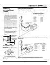
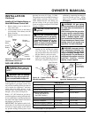
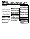
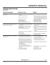
3. To open the glass door, open the pairs
of latches located on the top and bottom
of the firebox (see Figure 41).
Note:
Use
caution when opening these latches.
4. Carefully open the door. The glass door
is mounted to the firebox with 5 screws.
5. To remove the logs from the shrink
wrap, carefully cut the plastic around
the perimeter of the log. Do not try to
remove the logs from the package with-
out first cutting the plastic.
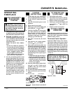
6. Figure 42 shows the log set. Logs “A”
have the knot at the end of the log. Logs
“B” have the knot at the middle of the
log. Twigs “C” have the shape of a “Y”.
Twigs “D” have the shape of bent twigs.
Twig “E” is a straight twig which is
placed across the top of Logs “B”.
Open
Close
Figure 41 - Removing Glass Door
GAS SUPPLY TESTING
Note:
This section is intended as a guide for
qualified service technicians installing gas
to the appliance.
CAUTION: Do not connect
appliance before pressure test-
ing gas piping. Damage to the
gas valve may result and an un-
safe condition may be caused.
O
F
F
P
I
L
O
T
O
N
L
O
H
I
P
I
L
O
T
EA
16AI
7
TPTH TP TH
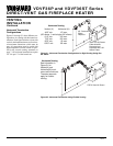
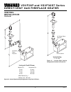
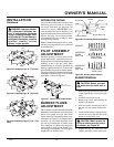
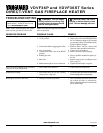
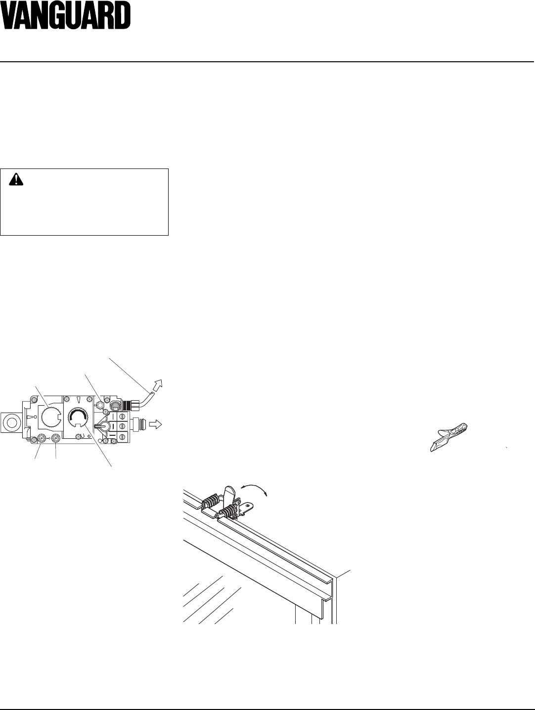
Figure 40 - Millivolt Control Valve
Pilot Gas Line - Do Not Kink
To Pilot
BurnerPilot Adjustment Cap
ON/OFF
Knob
To Main
Burner
Flame Adjustment
Knob
Outlet
Pressure
Inlet
Pressure
The millivolt system with a manual HI/LO
applies only to the VDVF36STN/STP and
VDVF36PN/PP models. The gas control
valve is secured underneath the firebox with
two brackets fastened to the firebox bottom.
Two pressure taps are provided on the gas
control valve for a pressure gauge connec-
tion (see Figure 40).
7. Figure 43, page 19, shows the top view
of the burner and grate.
8. Place logs “A” as shown in Figure 44,
page 19.
9. Place logs “B” as shown in Figure 45,
page 19. Lift the end of log “A” that will
be propped up and place log “B” under
it. At the same time, the other side of
log “B” is placed over the other log “A”.
Repeat procedure for the other log “B”.
10. Take twigs “C” (shaped like a “Y”)
and place them as shown in Figure 46,
page 19.
11. Take twigs “D” (bent twig) and place
them as shown in Figure 46, page 19.
12. Place twig “E” across the top of logs
“B” a shown in Figure 46, page 19.
13. When finished installing the logs, close
the glass doors while making certain that
the safety door switch is fully depressed
by the door frame before securing the
four (4) spring loaded latches.
14. Replace the louvers in reverse order
with the grilles pointing in the down
position.