


17
105706
OWNER’S MANUAL
INSTALLATION
Continued
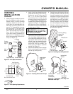
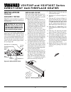
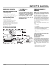
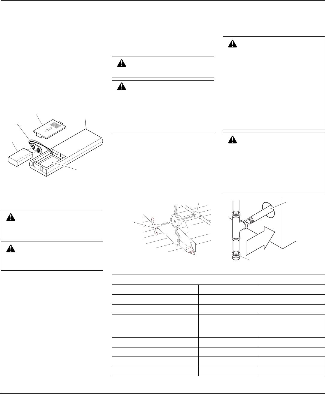
Installing 9-Volt Alkaline Battery in
Hand-Held Remote Control Unit
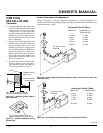
1. Remove battery cover on back of re-
mote control unit.
2. Attach terminal wires to the battery
(not included). Place battery into the
battery housing.
3. Replace battery cover onto remote con-
trol unit.
Figure 37 - Installing Battery in Hand-
Held Remote Control Unit
Battery
Cover
9-Volt
Battery
Terminal
Wires
Remote
Control Unit
Battery
Housing
Continued
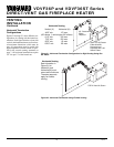
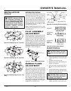
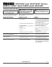
GAS LINE HOOK-UP
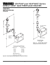
Figure 38 - Typical Exterior Wall Gas
Shut-Off Installation
WARNING: Gas line hookup
should be done by your gas sup-
plier or a qualified service person.
WARNING: Before you pro-
ceed, make sure your gas supply
is OFF.
A manual shut-off valve has been included
in the appliance’s gas supply system. You
may consider installing an extra gas shut-off
valve outside the appliance’s enclosure
(check with local codes) where it can be
accessed more conveniently with a key
through a wall as shown in Figure 38.
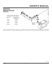
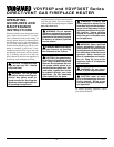
Route a 1/2” NPT black iron gas line to-
wards the appliance coming in from the left.
It is recommended to route the pipe between
the stand of the firebox and the surround of
the fireplace (see Figure 39).
IMPORTANT:
The appliance and its indi-
vidual shut-off valve must be disconnected
from the gas supply piping system during
any pressure testing of that system at test
Key
Extension
Shut-Off Valve
CAUTION: Compounds used
on threaded joints of gas piping
shall be resistant to the action of
Liquefied Petroleum (LP or pro-
pane), and should be applied
lightly to ensure excess sealant
does not enter the gas line.
CAUTION: Do not kink flex-
ible gas line.
pressures in excess of 1/2 psig. (3.5 kPa).
The appliance must be isolated from the gas
supply piping system by closing its indi-
vidual manual shut-off valve during any
pressure testing of the gas supply piping
system at test pressures equal to or less than
1/2 psig. (3.5 kPa).
WARNING: All gas piping
and connections must be tested
for leaks after the installation is
completed.
After ensuring that the gas valve
is open, apply a soap and water
solution to all connections and
joints. If bubbles appear, leaks
can be detected and corrected.
Do not use an open flame for leak
testing and do not operate any
appliance if a leak is detected.
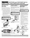
Back Wall
Of Appliance
Incoming 1/2"
Gas Line
Permitted by
Local Codes
Sediment Trap (Not Supplied)
Figure 39 - Sediment Trap
WARNING: Improper installa-
tion, adjustment, alteration, ser-
vice, or maintenance can cause
injury or property damage. Refer
to this manual. For assistance or
additional information, consult a
qualified installer, service
agency, or gas supplier.
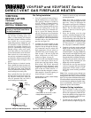
GAS RATING
TYPE OF GAS NATURAL PROPANE/LP
Max. Input Rating: 30,000 Btu/hr 28,000 Btu/hr
Orifice Size (0-4,500 Ft.): 7/64" #52
Minimum Input Rating: 21,000 Btu/hr 20,000 Btu/hr
(When the Valve is in
the LOW Position)
* Maximum Output Rating: 21,000 Btu/hr 20,000 Btu/hr
Manifold Pressure: 3.5 in. WC 10.0 in. WC
**Minimum Supply Pressure: 4.5 in. WC 11.0 in. WC
**Maximum Supply Pressure: 10.5 in. WC 13.0 in. WC
1. Install a sediment trap between the in-
coming gas line and the gas control
valve (see Figure 39). The sediment
trap should extend down the center of
the pipe. Refer to your local codes.
2. Prepare incoming gas line and check
with local codes regarding the use of
teflon tape. Complete your gas line in-
stallation by connecting incoming gas
line with flexible gas line. Secure
tightly with a wrench, but Do NOT
Overtighten.
* 70% Efficiency (flue loss calculation).
** For the purpose of input adjustment.