


16
105706
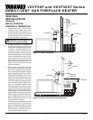
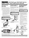
DIRECT-VENT GAS FIREPLACE HEATER
VDVF36P and VDVF36ST Series
®
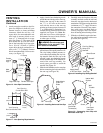
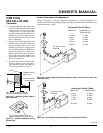
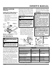
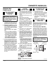
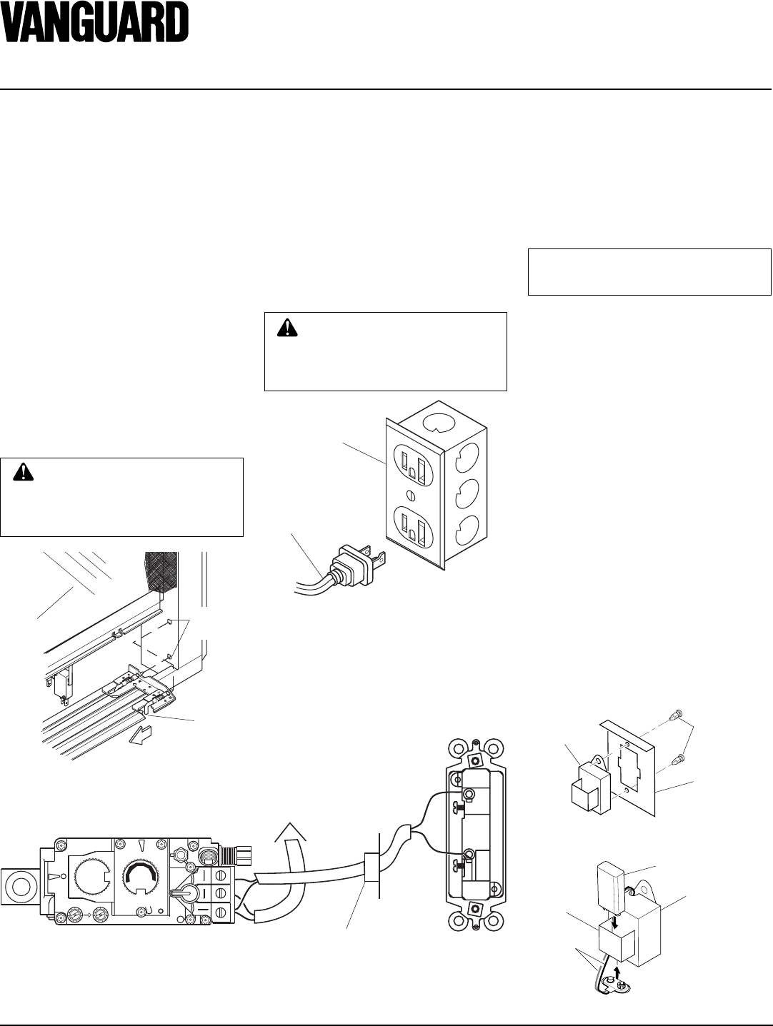
Figure 33 - Wall Switch Wiring Diagram
OPTIONAL WIRELESS HAND-
HELD REMOTE CONTROL
(GHRC(T) SERIES)
INSTALLATION
Note:
If using an optional wireless hand-
held remote control, the wall switch is no
longer operational.
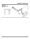
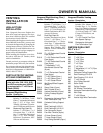
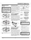
Figure 35 - Installing Remote Receiver
(Shown from Rear of Mounting Bracket)
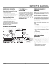
Figure 36 - Installing Battery in Receiver
INSTALLATION
WARNING: Do not wire re-
mote wall switch to main power
supply (Standard 120v household
current).
WALL SWITCH
INSTALLATION
Since the VDVF36 series models use a
valve that operates on millivolt current gen-
erated by the pilot, a wall switch may be
used to activate the gas control valve with-
out the use of normal household electricity.
1. To remove the louvers, simultaneously
pull both top end spring latches towards
the center of the appliance until they
are disengaged from locating holes.
Repeat for bottom end spring latches
and pull outward. Reverse the proce-
dure to install louvers back onto the
appliance (see Figure 32).
2. Connect the 18 ga. wires from wall
switch to the gas control valve and
microswitch, as shown in Figure 33.
O
F
F
P
I
L
O
T
O
N
L
O
H
I
P
I
L
O
T
EA
16AI
7
TPTH TP TH
Wall Switch
(Supplied)
Route Millivolt Wires (Supplied)
Through Gas Line Conduit Sleeve
To
Thermopile
(Back View)
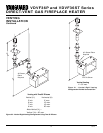
ELECTRICAL HOOKUP FOR
BLOWER ACCESSORY
Before blower accessory can be operated, it
must be properly connected to a standard
120 VAC power source. Refer to Wiring
Diagram on page 23.
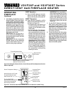
An outlet box with two receptacles has been
supplied for your convenience, located on
the lower left side of the appliance (see
Figure 34). An optional remote control may
be installed at any time.
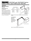
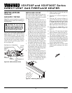
Figure 34 - Connecting Blower Accessory
to Power Supply
For Optional
Fan Kit
From Blower
Assembly
Note:
If any of the original wire supplied must be replaced, use type 18 AWG-105 degree
C (25 feet length MAXIMUM) or equivalent.
CAUTION: Due to high tem-
peratures, make sure no wires
are touching the bottom of the
firebox.
Figure 32 - Removing Louver
Glass
Locating
Holes
Spring
Latch
NOTICE: Only use alkaline bat-
teries (not included).
Installing Receiver
1. Remove access panel from lower front
face of firebox. Lift straight up on ac-
cess panel until it stops. Pull bottom of
access panel forward, then down.
2. Disconnect wall switch wires from TH
and TPTH terminals on control valve
(see Figure 33).
3. Install remote receiver unit onto mount-
ing bracket using the two plastic mount-
ing clips (see Figure 35).
4. Connect wires to control valve. Con-
nect white wire to terminal TH. Con-
nect red wire to terminal TPTH.
5. Locate the battery clip mounted on the
back of the receiver (see Figure 36).
6. Slide 9-volt battery (not included)
through the clip.
7. Attach the terminal wires to the battery
(see Figure 36).
8. Replace access panel. Place top of ac-
cess panel into opening and slide up.
Push bottom of access panel in and
slide down to install.
Battery Clip
9-Volt Battery
Receiver
Terminal
Wires
Receiver
Mounting
Bracket
Plastic
Mounting
Clips