


www.desatech.com
115121-01B6
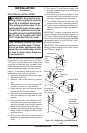
ELECTRICAL INSTALLATION
WARNING: Any electrical re-
wiring of this appliance must be
done by a qualied electrician.
This wiring must be done in ac-
cordance with local codes and/or
in the U.S.A. with the current, Na-
tional Electrical Code ANSI/NFPA
No 70 and in Canada with CSA
C22.1 Canadian Electric code.
This replace should be con-
nected to a dedicated 15 Amp,
circuit as other appliances may
cause the circuit breaker to trip
or fuse to blow when replace
is in operation.
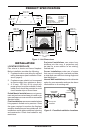
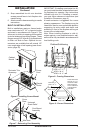
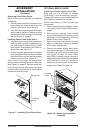
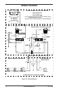
A junction box with universal strain adaptor
is provided to hard wire unit to a 15 amp,
120 Volt 60 Hz grounded circuit. Power cord
must rst be removed and universal strain
relief bushing inserted into junction box cover
before connecting supply line (see Figure 7,
page 5). If necessary, junction box may be
relocated to route supply to left side.
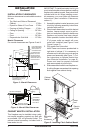
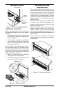
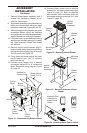
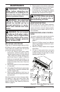
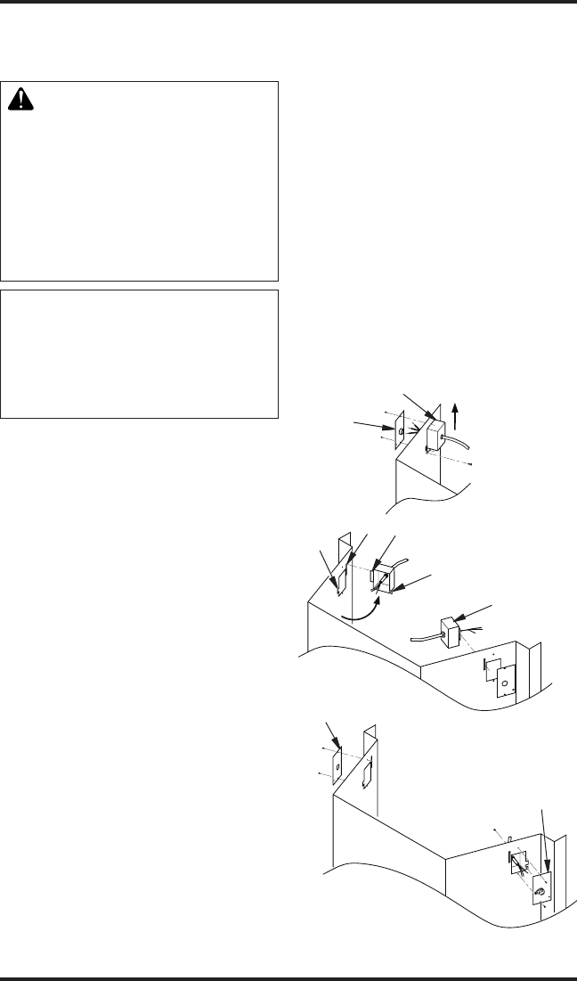
1. Remove 2 screws and outer cover on right
side (see Figure 10).
2. Remove inner screw securing junction
box.
3. Slide junction box up until mounting tab
is lined up to notch in outer cabinet.
4. Swing box out and slip retaining ange
out through slot in outer cabinet.
5. Remove 2 screws and outer cover on left
side and reattach on right side of outer
cabinet.
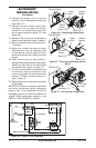
6. Swing junction box with harness to left
side while pulling sufcient length of har-
ness out through control panel cover to
reach mounting location on left side.
7. Reinsert retaining ange through slot and
swing screw mounting tab back through
notch as before.
8. Slide junction box down until mounting
holes line up and replace inner retaining
cover.
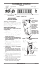
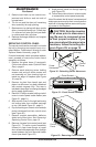
9. Pull end of 3 wire Romex supply line
through universal strain relief bushing in
remaining cover.
10. Strip back outer Romex to about 4” and
connect black, white and green wires ac-
cordingly using approved connectors.
11. Tuck tailing wires into junction box and
replace cover using 2 remaining screws.
12. Tighten down strain adjustment on uni-
versal bushing until Romex sheathing is
secured.
IMPORTANT: Inspect components and wir-
ing for damage before connecting power to
unit. If any components are found damaged,
contact an authorized dealer for original DESA
replacement part(s) or call DESA at 1-866-
872-6040 for referral.
IMPORTANT: Prior to operation remove foam
shipping brace located under motor mount
(see Figure 11, page 7).
Screws
and
Outer
Cover
Junction Box
Mounting
Tab
Notch
Retaining
Flange
Slot
Screws and
Outer Cover
from Other Side
Cover with
Universal
Strain Relief
Figure 10 - Relocating Junction Box to
Left
INSTALLATION
Continued
Junction Box