


www.desatech.com
115121-01B4
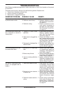
INSTALLATION CLEARANCES
Minimum clearances to combustible construc-
tion are:
• Top, Back and Sides of Recessed
Cabinet . . . . . . . . . . . . . . . . . . . . .0" Min.
• Drywall to Sides of Front Face . . .0" Min.
• Framing at Nailing Flanges . . . . . .0" Min.
• Ceiling to Opening . . . . . . . . . . . .36" Min.
• Floor . . . . . . . . . . . . . . . . . . . . . . .0" Min.
• Front . . . . . . . . . . . . . . . . . . . . . .36" Min.
• Perpendicular Side Wall . . . . . . .10" Min.
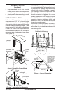
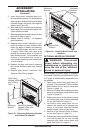
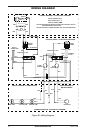
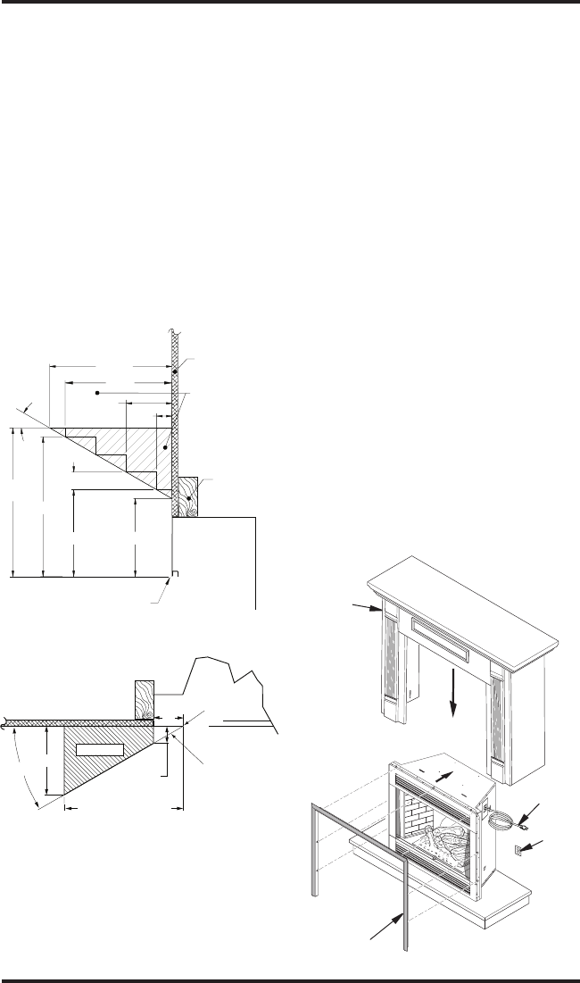
Mantel Clearances
For mantel clearances see Figures 3 and 4.
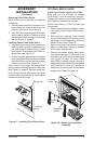
CABINET MANTEL INSTALLATION
This replace may be installed using a cabi-
net mantel accessory against any wall with
an available 120 volt grounded outlet. The
cabinet mantel accessory includes both a
base and a trim kit.
INSTALLATION
Continued
Facing Material May
Be Noncombustible
Wall Treatments or
Combustible Wood
Combustible Wood
Mantels and Trims
May Extend Above
Profile Shown when
Maintained within 30°
Parameter Shown
Framed
Material
Top of Cabinet
Note: All Mantel Clearances
are Measured from Top of
Fireplace Opening
30°
16
5
/
8
"
Ref.
9
5
/
8
" Ref.
12" Ref.
13
3
/
4
"
4
1
/
2
"
1
1
/
2
"
1
3
/
4
"
10
1
/
2
" Min.
10
1
/
2
"
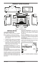
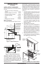
Figure 3 - Mantel Clearances
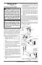
Top View of Fireplace
Safe Zone
5"
3"
30°
1
3
/
4
" Max.
Minimum 10" from
Perpendicular Side Wall
Edge of Firebox
Opening
Combustible
MaterialMust
Not Overlap
Front Face
Figure 4 - Mantel Side Clearances
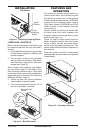
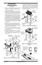
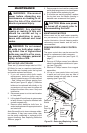
Figure 5 - Installing Flush Cabinet Mantel
Cabinet
Mantel
Perimeter
Trim
Accessory
Electric
Outlet
Power
Cord
IMPORTANT: To install perimeter trim kit, you
must install shoulder screws before installing
replace into cabinet mantel. See instructions
included with trim kit. When installing a man-
tel accessory, you must follow all clearance
instructions (see Installation Clearances,
column 1).
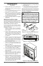
1. Assemble cabinet mantel accessory and
trim kit by following assembly instructions
included with each kit.
2. Place hearth base close to wall at desired
location. Leave enough room to get be-
hind unit and attach mantel to base once
replace and mantel has been placed.
When possible, location should be within
3" of power outlet so mantel will cover
outlet with installed (see Figure 5 and
Figure 6, page 5).
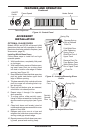
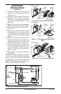
3. Plug power cord into outlet.
Note: Power cord comes preattached to
right side of cabinet. If it is necessary to
relocate cord to left side you must remove
power cord assembly (see Figure 7). Fol-
low instructions to relocate junction box
(see Electrical Installation, on page 6).
Power cord must be properly mounted
and reconnected at junction box.
4. Slide assembled mantel over replace un-
til nailing anges are centered into opening
ush against rear cabinet facing.