


www.desatech.com
115121-01B 21
MAINTENANCE
Continued
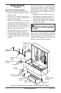
14. Center log bed over opening between
viewing panel screen and grate.
15. Cover remaining hearth area with 1/4" of
lava rock (provided), if desired.
CLEANING VIEWING SCREEN
Clean viewing screen with an alcohol based,
nonabrasive, residue free cleaner (premoist-
ened hand wipes are ideal). Do not use glass
cleaners with ammonium, abrasive scrubs or
degreaser solvents of any kind.
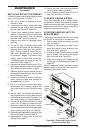
ACCESSING IMAGING UNIT FOR
REPLACEMENT
The imaging unit can be removed from inside
the rebox for servicing or replacement:
1. Follow steps under Accessing Imaging
Unit, on page 17.
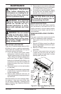
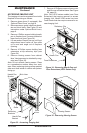
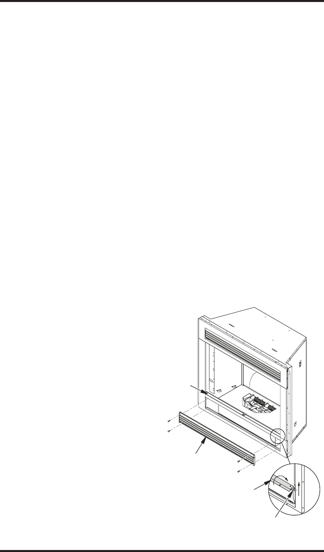
2. Remove 4 hex screws on lower louver
panel and detach louver assembly from
front face (see Figure 40).
3. Rotate top edge of lower frame rail inward
and lift upward until locking tabs detach
from front face (see Figure 40).
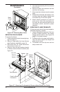
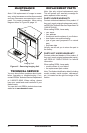
4. Slide entire imaging unit forward and lift
out through front opening (see Figure 41,
page 22).
Note: An additional 3 feet of harness is tucked
behind imager to permit removal without dis-
connecting any control wiring.
REPLACING REFLECTIVE RIBBONS
If reective ribbons become damaged or loose
they may be replaced as follows:
1. Turn off all power to replace at circuit
breaker or fuse.
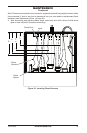
2. Locate defective ribbon; there are 3 strips
mounted on rear cabinet and 3 mounted
in base (see Figure 39, page 20).
3. If upper back cabinet ribbons need re-
placing, remove 4 Phillips screws holding
corresponding bottom and top hanger
brackets (see Figure 39, page 20).
4. Remove any loose or damaged ribbon
material.
5. Cut an 18” strip of reective ribbon and
position top end about an inch above top
bracket position (see Figure 39, page 20).
Note: Ribbon material should be ap-
plied with reective side up, should not
be twisted or tangled, and should hang
slightly loose to allow free movement.
If additional parts are required, see Re-
placement Parts, page 22.
6. Replace top hanger bracket using 2 Phil-
lips screws removed in step 2 and tighten
until reective ribbon is held in place.
7. Replace bottom hanger bracket using 2
remaining Phillips screws to secure lower
end of reective ribbon.
8. If replacing reective ribbons located in
base, remove screws and washers at
damaged ends of ribbon.
9. Cut a 9" long strip of ribbon and apply
across each ribbon support bracket with
shiny side facing up (see Figure 39, page
20).
10. Secure ribbon to brackets by replacing
each washer at end of the ribbon and re-
threading screws through the ribbon into
each hole located on support brackets.
11. If replacing top reective ribbons on base
cover, cut a 3" section of ribbon and split
down the middle. With shiny side up, attach
with cellophane tape into rear edge of base
cover opening (see Figure 39, page 20).
12. Readjust ame pennants (if removed). See
Servicing Flame Pennants, page 18.
13. Reassemble imager. See Accessing
Imaging Unit, page 17.
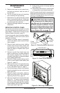
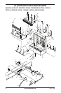
Figure 40 - Removing Lower Louver
Panel and Frame Rail
Lower Panel
Lower
Frame
Rail
Lower
Frame
Rail
Locking Tab