


www.desatech.com
115121-01B 5
INSTALLATION
Continued
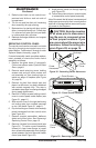
5. Snap assembled trim kit onto shoulder
screws around face to lock replace into
mantel facing.
6. Attach mantel to base according to mantle
instructions.
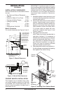
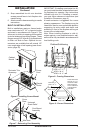
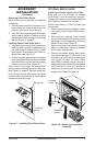
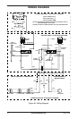
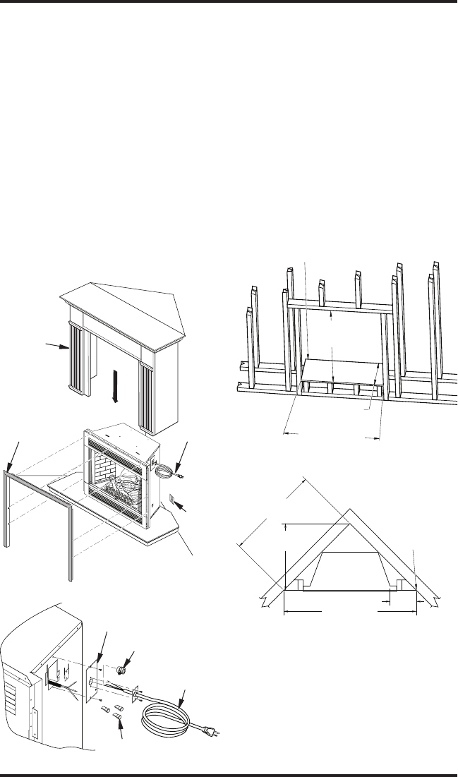
BUILT-IN INSTALLATION
Built-in installations require a framed enclo-
sure constructed of 2" x 4" or heavier lumber
and sized in accordance with Figure 8. This
allows unit to slide into opening and be nailed
to stud at sides and top nailing anges. These
anges accept 5/8" drywall or plywood board
to nish unit ush to face. Optional trim ac-
cessories are available that will extend 1/2"
over rough edge of wall opening (see Acces-
sories, page 23).
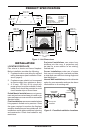
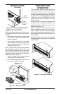
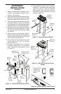
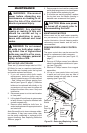
Figure 7 - Relocating Cord Assembly
Cover
Plate
Universal
Strain Relief
Cord Mount
Assembly
Wire Nuts
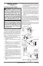
Figure 6 - Installing Corner Mantel
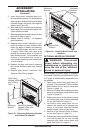
IMPORTANT: If installing a perimeter trim kit,
you must install shoulder screws before insert-
ing replace into opening. See instructions
included with trim kit. If installing a mantel,
you must follow clearance instructions (see
Installation Clearances, page 4).
A hearth extension is suggested for a more
pleasing appearance. The replace may be
raised on a wood or non-combustible platform
supporting its entire width and depth and
extending in front of the replace as long as
louvers are not obstructed.
Note: When installing replace in cold cli-
mates against a non-insulated exterior wall,
wall must be fully insulated in accordance with
local building code.
Electric
Outlet
Power
Cord
Perimeter Trim
Accessory
Cabinet
Mantel
VE32 = 34
5
/
8
"
VE36 = 41
1
/
4
"
VE32 = 15
7
/
8
"
VE36 = 17
1
/
4
"
VE32 = 32
5
/
8
"
VE36 = 36
1
/
4
"
Platform/Subflooring
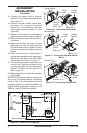
Figure 8 - Framing Dimensions
VE32 = 37
5
/
8
"
VE36 = 42
3
/
8
"
VE32 = 26
5
/
8
"
VE36 = 29
3
/
8
"
VE32 = 52
3
/
4
"
VE36 = 58
1
/
4
"
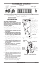
11
5
/
8
"
These Dimensions
Allow for 11
5
/
8
" of
Clearance to Side
Wall of Fireplace
and 10' Clearance
to Perpendicular
Side Walls
Figure 9 - Corner Dimensions